
R0106-HP MSR Router Series MPLS Configuration Guide(V7)


41
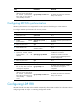
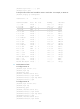
FEC In/Out Label Nexthop OutInterface
1.1.1.9/32 3/-
-/1279(L)
2.2.2.9/32 -/3 10.1.1.2 S2/1/0
1279/3 10.1.1.2 S2/1/0
3.3.3.9/32 -/1278 10.1.1.2 S2/1/0
1278/1278 10.1.1.2 S2/1/0
11.1.1.0/24 1277/-
-/1277(L)
21.1.1.0/24 -/1276 10.1.1.2 S2/1/0
1276/1276 10.1.1.2 S2/1/0
# Test the connectivity of the LDP LSP from Router A to Router C.
[RouterA] ping mpls -a 11.1.1.1 ipv4 21.1.1.0 24
MPLS Ping FEC: 21.1.1.0/24 : 100 data bytes
100 bytes from 20.1.1.2: Sequence=1 time=1 ms
100 bytes from 20.1.1.2: Sequence=2 time=1 ms
100 bytes from 20.1.1.2: Sequence=3 time=8 ms
100 bytes from 20.1.1.2: Sequence=4 time=2 ms
100 bytes from 20.1.1.2: Sequence=5 time=1 ms
--- FEC: 21.1.1.0/24 ping statistics ---
5 packets transmitted, 5 packets received, 0.0% packet loss
round-trip min/avg/max = 1/2/8 ms
# Test the connectivity of the LDP LSP from Router C to Router A.
[RouterC] ping mpls -a 21.1.1.1 ipv4 11.1.1.0 24
MPLS Ping FEC: 11.1.1.0/24 : 100 data bytes
100 bytes from 10.1.1.1: Sequence=1 time=1 ms
100 bytes from 10.1.1.1: Sequence=2 time=1 ms
100 bytes from 10.1.1.1: Sequence=3 time=1 ms
100 bytes from 10.1.1.1: Sequence=4 time=1 ms
100 bytes from 10.1.1.1: Sequence=5 time=1 ms
--- FEC: 11.1.1.0/24 ping statistics ---
5 packets transmitted, 5 packets received, 0.0% packet loss
round-trip min/avg/max = 1/1/1 ms
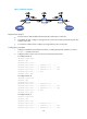
Label acceptance control configuration example
Network requirements
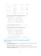
Two links, Router A—Router B—Router C and Router A—Router D—Router C, exist between subnets
11.1.1.0 / 24 a n d 21.1.1.0 / 24 .
Configure LDP to establish LSPs only for routes to subnets 11.1.1.0 / 24 a n d 21.1.1.0 / 24 .
Configure LDP to establish LSPs only on the link Router A—Router B—Router C to forward traffic between
subnets 11.1.1.0 / 24 a n d 21.1.1.0 / 24 .