
R0106-HP MSR Router Series MPLS Configuration Guide(V7)


45
[RouterC-ldp] quit
Verifying the configuration
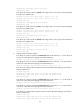
# Display LDP LSP information on routers, for example, on Router A.
[RouterA] display mpls ldp lsp
Status Flags: * - stale, L - liberal, B - backup
FECs: 2 Ingress: 1 Transit 1 Egress: 1
FEC In/Out Label Nexthop OutInterface
11.1.1.0/24 1277/-
-/1148(L)
21.1.1.0/24 -/1149(L)
-/1276 10.1.1.2 S2/1/0
1276/1276 10.1.1.2 S2/1/0
The output shows that the next hop of the LSP for FEC 21.1.1.0/24 is Router B (10.1.1.2). The LSP has been
established over the link Router A—Router B—Router C, not over the link Router A—Router D—Router C.
# Test the connectivity of the LDP LSP from Router A to Router C.
[RouterA] ping mpls -a 11.1.1.1 ipv4 21.1.1.0 24
MPLS Ping FEC: 21.1.1.0/24 : 100 data bytes
100 bytes from 20.1.1.2: Sequence=1 time=1 ms
100 bytes from 20.1.1.2: Sequence=2 time=1 ms
100 bytes from 20.1.1.2: Sequence=3 time=8 ms
100 bytes from 20.1.1.2: Sequence=4 time=2 ms
100 bytes from 20.1.1.2: Sequence=5 time=1 ms
--- FEC: 21.1.1.0/24 ping statistics ---
5 packets transmitted, 5 packets received, 0.0% packet loss
round-trip min/avg/max = 1/2/8 ms
# Test the connectivity of the LDP LSP from Router C to Router A.
[RouterC] ping mpls -a 21.1.1.1 ipv4 11.1.1.0 24
MPLS Ping FEC: 11.1.1.0/24 : 100 data bytes
100 bytes from 10.1.1.1: Sequence=1 time=1 ms
100 bytes from 10.1.1.1: Sequence=2 time=1 ms
100 bytes from 10.1.1.1: Sequence=3 time=1 ms
100 bytes from 10.1.1.1: Sequence=4 time=1 ms
100 bytes from 10.1.1.1: Sequence=5 time=1 ms
--- FEC: 11.1.1.0/24 ping statistics ---
5 packets transmitted, 5 packets received, 0.0% packet loss
round-trip min/avg/max = 1/1/1 ms
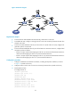
Label advertisement control configuration example
Network requirements
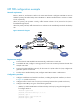
Two links, Router A—Router B—Router C and Router A—Router D—Router C, exist between subnets
11.1.1.0 / 24 a n d 21.1.1.0 / 24 .
Configure LDP to establish LSPs only for routes to subnets 11.1.1.0 / 24 a n d 21.1.1.0 / 24 .