
R0106-HP MSR Router Series Voice Configuration Guide(V7)

107
# Configure local number 1111 for POTS entity 1111 and bind FXS interface 2/2/1 to the POTS
entity.
[RouterA-voice-dial] entity 1111 pots
[RouterA-voice-dial-entity1111] line 2/2/1
[RouterA-voice-dial-entity1111] match-template 1111
2. Configure Router B:
# Configure an IP address for GigabitEthernet 2/1/1.
<RouterB> system-view
[RouterB] interface gigabitethernet 2/1/1
[RouterB-GigabitEthernet2/1/1] ip address 192.168.2.2 255.255.255.0
[RouterB-GigabitEthernet2/1/1] quit
# Configure local number 2222 for POTS entity 2222 and bind FXS interface 2/2/1 to the POTS
entity.
<RouterB> system-view
[RouterB] voice-setup
[RouterB-voice] dial-program
[RouterB-voice-dial] entity 2222 pots
[RouterB-voice-dial-entity2222] line 2/2/1
[RouterB-voice-dial-entity2222] match-template 2222
[RouterB-voice-dial-entity2222] quit
# Configure the destination address 192.168.2.1 and number 1111 for the VoIP entity 1111.
[RouterB-voice-dial]entity 1111 voip
[RouterB-voice-dial-entity1111] address sip ip 192.168.2.1
[RouterB-voice-dial-entity1111] match-template 1111
Verifying the configuration
# Place calls to verify that phone 1111 and phone 2222 can call each other.
# Execute the display voice sip call command to display the SIP call information.
Configuring SIP to use TCP as the transport protocol
Network requirements
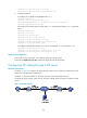
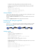
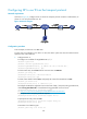
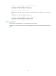
As shown in Figure 38, configure SIP to use TCP as the transport protocol on Router A and Router B, so
phone 1111 can call phone 2222 over TCP.
Figure 38 Network diagram
Configuration procedure
1. Configure Router A:
# Configure an IP address for GigabitEthernet 2/1/1.
<RouterA> system-view
[RouterA] interface gigabitethernet 2/1/1
[RouterA-GigabitEthernet2/1/1] ip address 192.168.2.1 255.255.255.0