
R0106-HP MSR Router Series Voice Configuration Guide(V7)

112
Configuring out-of-band DTMF
Network requirements
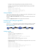
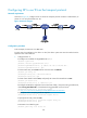
As shown in Figure 40, configure Router A and Router B to use out-of-band signaling to transmit DTMF
tones so the phones 1111 and 2222 can call each other.
Figure 40 Network diagram
Configuration procedure
1. Configure Router A:
# Configure an IP address for GigabitEthernet 2/1/1.
<RouterA> system-view
[RouterA] interface gigabitethernet 2/1/1
[RouterA-GigabitEthernet2/1/1] ip address 192.168.2.1 255.255.255.0
[RouterA-GigabitEthernet2/1/1] quit
# Configure call destination address 192.168.2.2 and number 2222 for VoIP entity 2222.
[RouterA] voice-setup
[RouterA-voice] dial-program
[RouterA-voice-dial] entity 2222 voip
[RouterA-voice-dial-entity2222] address sip ip 192.168.2.2
[RouterA-voice-dial-entity2222] match-template 2222
# Configure out-of-band DTMF for VoIP entity 2222.
[RouterA-voice-dial-entity2222] outband sip
[RouterA-voice-dial-entity2222] quit
# Configure local number 1111 for POTS entity 1111 and bind FXS interface 2/2/1 to the POTS
entity.
[RouterA-voice-dial] entity 1111 pots
[RouterA-voice-dial-entity1111] line 2/2/1
[RouterA-voice-dial-entity1111] match-template 1111
# Configure out-of-band DTMF for POTS entity 1111.
[RouterA-voice-dial-entity1111] outband sip
2. Configure Router B:
# Configure an IP address for GigabitEthernet 2/1/1.
<RouterB> system-view
[RouterB] interface gigabitethernet 2/1/1
[RouterB-GigabitEthernet2/1/1] ip address 192.168.2.2 255.255.255.0
[RouterB-GigabitEthernet2/1/1] quit
# Configure call destination address 192.168.2.1 and number 1111 for VoIP entity 1111.
[RouterB] voice-setup
[RouterB-voice] dial-program
[RouterB-voice-dial] entity 1111 voip
[RouterB-voice-dial-entity1111] address sip ip 192.168.2.1