
R0106-HP MSR Router Series Voice Configuration Guide(V7)

13 0
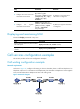
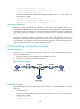
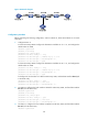
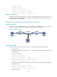
Figure 49 Network diagram
Configuration procedure
Before performing the following configuration, make sure Router A, Router B and Router C can reach
each other.
1. Configure Router A:
# Create VoIP entity 2000. Configure the destination IP address as 10.1.1.2, and configure the
called number as 2000.
<RouterA> system-view
[RouterA] voice-setup
[RouterA-voice] dial-program
[RouterA-voice-dial] entity 2000 voip
[RouterA-voice-dial-entity2000] address sip ip 10.1.1.2
[RouterA-voice-dial-entity2000] match-template 2000
[RouterA-voice-dial-entity2000] quit
# Create VoIP entity 3000. Configure the destination IP address as 20.1.1.2, and configure the
called number as 3000.
[RouterA-voice-dial] entity 3000 voip
[RouterA-voice-dial-entity3000] address sip ip 20.1.1.2
[RouterA-voice-dial-entity3000] match-template 3000
[RouterA-voice-dial-entity3000] quit
# Configure the local number as 1000 for POTS entity 1000, and bind FXS interface line 2/1/1
to the POTS entity.
[RouterA-voice-dial] entity 1000 pots
[RouterA-voice-dial-entity1000] line 2/1/1
[RouterA-voice-dial-entity1000] match-template 1000
2. On Router B, configure the local number as 2000 for POTS entity 2000, and bind FXS interface
line 2/1/1 to the POTS entity.
<RouterB> system-view
[RouterB] voice-setup
[RouterB-voice] dial-program
[RouterB-voice-dial] entity 2000 pots
[RouterB-voice-dial-entity2000] line 2/1/1
[RouterB-voice-dial-entity2000] match-template 2000
3. On Router C, configure the local number as 3000 for POTS entity 3000, and bind FXS interface
line 2/1/1 to the POTS entity.
<RouterC> system-view