
R0106-HP MSR Router Series Voice Configuration Guide(V7)

131
[RouterC] voice-setup
[RouterC-voice] dial-program
[RouterC-voice-dial] entity 3000 pots
[RouterC-voice-dial-entity3000] line 2/1/1
[RouterC-voice-dial-entity3000] match-template 3000
Verifying the configuration
Verify that Telephone B and Telephone C can establish a call by using call transfer.
Call backup configuration example
Network requirements
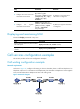
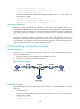
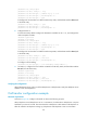
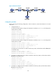
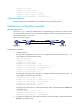
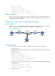
As shown in Figure 50, Router A and Router B are connected through two IP links. One of the two links
has a higher priority and serves as the primary link. Configure call backup so when the primary link goes
down, the backup link can take over.
Figure 50 Network diagram
Configuration procedure
1. Configure Router A:
# Create VoIP entity 2000 with a priority of 1. Configure the destination IP address as 10.1.1.2,
and configure the called number as 2000.
<RouterA> system-view
[RouterA] voice-setup
[RouterA-voice] dial-program
[RouterA-voice-dial] entity 2000 voip
[RouterA-voice-dial-entity2000] address sip ip 10.1.1.2
[RouterA-voice-dial-entity2000] match-template 2000
[RouterA-voice-dial-entity2000] priority 1
[RouterA-voice-dial-entity2000] quit
# Create VoIP entity 3000 with a priority of 2. Configure the destination IP address as 20.1.1.2,
and configure the called number as 2000.
[RouterA-voice-dial] entity 3000 voip
[RouterA-voice-dial-entity3000] address sip ip 20.1.1.2
[RouterA-voice-dial-entity3000] match-template 2000
[RouterA-voice-dial-entity2000] priority 2
[RouterA-voice-dial-entity3000] quit
# Configure the local number as 1000 for POTS entity 1000, and bind FXS interface line 2/1/1
to the POTS entity.
[RouterA-voice-dial] entity 1000 pots
[RouterA-voice-dial-entity1000] line 2/1/1
[RouterA-voice-dial-entity1000] match-template 1000
2. On Router B, configure the local number as 2000 for POTS entity 2000, and bind FXS interface
line 2/1/1 to the POTS entity.