
R0106-HP MSR Router Series Voice Configuration Guide(V7)

132
<RouterB> system-view
[RouterB] voice-setup
[RouterB-voice] dial-program
[RouterB-voice-dial] entity 2000 pots
[RouterB-voice-dial-entity2000] line 2/1/1
[RouterB-voice-dial-entity2000] match-template 2000
Verifying the configuration
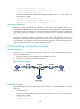
When the primary link (corresponding to VoIP entity 2000) fails, place a call from Telephone A to
Telephone B to verify that Telephone A can establish a call with Telephone B through the backup link
(corresponding to VoIP entity 3000).
Three-party conference configuration example
Network requirements
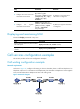
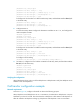
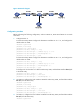
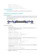
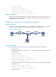
As shown in Figure 51, configure Router A, Router B, and Router C so that Telephone B as the conference
initiator can establish a three-party conference with Telephone A and Telephone C.
Figure 51 Network diagram
Configuration procedure
Make sure Router A, Router B, and Router C can reach each other before you configure them.
1. Configure Router A:
# Configure the destination IP address as 10.1.1.2 for VoIP entity 2000, and configure the called
number as 2000.
<RouterA> system-view
[RouterA] voice-setup
[RouterA-voice] dial-program
[RouterA-voice-dial] entity 2000 voip
[RouterA-voice-dial-entity2000] address sip ip 10.1.1.2
[RouterA-voice-dial-entity2000] match-template 2000
[RouterA-voice-dial-entity2000] quit
# Configure the local number as 1000 for POTS entity 1000, and bind FXS interface line 2/1/1
to the POTS entity.
[RouterA-voice-dial] entity 1000 pots
[RouterA-voice-dial-entity1000] line 2/1/1
[RouterA-voice-dial-entity1000] match-template 1000
2. Configure Router B: