
R0106-HP MSR Router Series Voice Configuration Guide(V7)

143
Ste
p
Command
Remarks
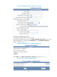
3. Enter dial program view.
dial-program N/A
4. Enter voice entity view.
entity entity-number { pots |
voip }
N/A
5. Configure modem
pass-through.
modem passthrough { nse
[ payload-type number ] |
protocol } codec { g711alaw |
g711ulaw }
By default, modem pass-through is not
used.
FoIP configuration examples
This section provides FoIP configuration examples.
Configuring FoIP
Network requirements
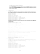
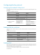
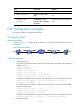
As shown in Figure 58, configure Router A and Router B to use the standard T.38 protocol for fax
transmission.
Figure 58 Network diagram
Configuration procedure
1. Configure Router A:
# Configure the called fax number as 2000 for VoIP entity 2000, and configure the destination IP
address as 2.2.2.2.
<RouterA> system-view
[RouterA] voice-setup
[RouterA-voice] dial-program
[RouterA-voice-dial] entity 2000 voip
[RouterA-voice-dial-entity2000] match-template 2000
[RouterA-voice-dial-entity2000] address sip ip 2.2.2.2
# Configure the standard T.38 protocol for VoIP entity 2000, with a low redundancy value of 4.
[RouterA-voice-dial-entity2000] fax protocol standard-t38 ls-redundancy 4
[RouterA-voice-dial-entity2000] quit
# Configure the local fax number as 1000 for POTS entity 1000, and bind FXS interface line
2/1/1 to the POTS entity.
[RouterA-voice-dial] entity 1000 pots
[RouterA-voice-dial-entity1000] match-template 1000
[RouterA-voice-dial-entity1000] line 2/1/1
# Configure the standard T.38 protocol for POTS entity 1000, with a low redundancy value of 4.
[RouterA-voice-dial-entity1000] fax protocol standard-t38 ls-redundancy 4
2. Configure Router B: