
R0106-HP MSR Router Series Voice Configuration Guide(V7)

16
Step Command Remarks
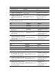
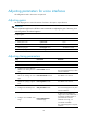
3. Enable E&M control signals
pass-through.
passthrough
By default, this function is disabled.
Configure this command on both
the originating and terminating
devices.
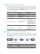
Configuring the output gain of SLIC chip
Step Command Remarks
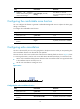
1. Enter system view.
system-view N/A
2. Enter voice interface view.
subscriber-line line-number N/A
3. Configure the output gain of
the SLIC chip.
slic-gain { 0 | 1 }
Optional.
The default is 0 (0.8 dB).
This command controls signal
amplification.
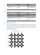
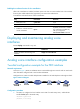
Configuring DTMF
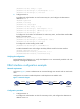
Dual tone multifrequency (DTMF) uses a mixture of a high frequency tone and a lower frequency tone to
represent a key on a keypad. Each column of keys is represented by a high frequency tone and each row
of keys is represented by a low frequency tone. For example, as shown in Figure 7, the di
git 1 i
s
represented by the combination of a pure 697 Hz signal and a pure 1209 Hz signal. These DTMF tones
offer good immunity to interference.
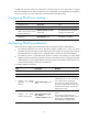
Figure 7 DTMF keypad frequencies
4
1 2 3 A
B65
7 8 9
*
0 #
C
D
1209Hz 1336Hz 1477Hz 1633Hz
697Hz
770Hz
852Hz
941Hz
Column Frequency Group