
R0106-HP MSR Router Series Voice Configuration Guide(V7)

23
[RouterA-voice-dial] entity 1001 pots
[RouterA-voice-dial-entity1001] match-template 0101001
[RouterA-voice-dial-entity1001] line 2/1/1
2. Configure Router B:
# Configure the called number as 010 for VoIP entity 010, and configure the destination IP
address as 1.1.1.1.
<RouterB> system-view
[RouterB] voice-setup
[RouterB-voice] dial-program
[RouterB-voice-dial] entity 010 voip
[RouterB-voice-dial-entity10] match-template 0101001.
[RouterB-voice-dial-entity10] address sip ip 1.1.1.1
[RouterB-voice-dial-entity10] quit
# Configure the local number as 07552001 for POTS entity 2001, and bind FXO interface line
2/1/1 to the POTS entity.
[RouterB-voice-dial] entity 2001 pots
[RouterB-voice-dial-entity2001] match-template 07552001
[RouterB-voice-dial-entity2001] line 2/1/1
# Configure the number sending mode as all.
[RouterB-voice-dial-entity2001] send-number all
# Enable the PLAR function and configure the delay off-hook mode for the FXO interface.
[RouterB] subscriber-line 2/1/1
[RouterB-subscriber-line2/1/1] private-line 0101001
[RouterB-subscriber-line2/1/1] hookoff-mode delay
Verifying the configuration
Dial 07552003 from Telephone B to verify that Telephone B can automatically establish calls with
Telephone A through the PLAR function.
E&M interface configuration example
Network requirements
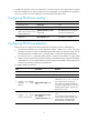
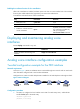
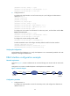
As shown in Figure 11, Router A and Router B are connected through an IP network and can reach each
other.
Configure the two routers to enable Telephone A and Telephone B to establish calls.
Figure 11 Network diagram
Configuration procedure
1. Configure Router A:
# Configure the called number as 0755 for VoIP entity 0755, and configure the destination IP
address as 2.2.2.2.
07552001
IP network
Router A Router B
Telephone A
FXS2/1/1 E&M2/3/11.1.1.1/24 2.2.2.2/24
PBX
0101001
Telephone B