
R0106-HP MSR Router Series Voice Configuration Guide(V7)

35
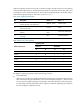
Digital line signaling sets the line to be idle or seized according to the state of the trunk. This signaling
is transmitted through timeslot 16. The two transmission directions of each line have four bits (A, B, C and
D) as flag bits, with C and D bits fixed to 01. The forward line signaling adopts a
f
and b
f
bits, and the
backward line signaling adopts a
b
and b
b
bits, as shown in Table 2:
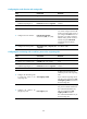
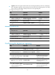
Table 2 Line signaling bit description
Bit Description Value = 0 Value = 1
a
f
Identifies the state of the originating device and
indicates the state of the calling line.
Off-hook, seized On-hook (idle)
b
f
Indicates a fault state from the originating side to
the terminating side.
Normal Faulty
a
b
Indicates the state of the called line (on-hook or
off-hook).
Off-hook by called
party
On-hook by called party
b
b
Indicates the state of the terminating device (idle
or seized).
Idle Seized or blocked
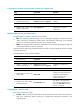
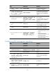
Table 3 State code of line signaling
State of the circuit
Signaling code
Forward Backward
a
f
b
f
a
b
b
b
Idle or release 1 0 1 0
Seized 0 0 1 0
Seizure-ack 0 0 1 1
Answer 0 0 0 1
Clear-back 0 0 1 1
Clear-forward 1 0 0/1 1
Blocked 1 0 1 1
Unblocked 1 0 1 0
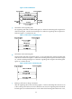
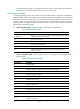
R2 digital line signaling exchange includes the following processes:
• Call establishment.
When the circuit is idle, the originating side sends a forward seizure signal (00) to the terminating
side, and the terminating side sends back a seizure acknowledgement signal (11). Then the circuit
is seized, and interregister signaling exchange begins. When the called party picks up the phone,
the terminating side sends a backward answer signal (01). After the originating side recognizes
the received signal, it establishes the call.