
R0106-HP MSR Router Series Voice Configuration Guide(V7)

45
Step Command
1. Enter system view.
system-view
2. Enter E1 or T1 interface view.
controller { e1 | t1 } number
3. Bundle timeslots into a PRI set.
pri-set [ timeslots-list range ]
Binding a digital voice interface to a POTS entity
Step Command Remarks
1. Enter system view.
system-view N/A
2. Enter voice view.
voice-setup N/A
3. Enter voice dial program view.
dial-program N/A
4. Create a POTS entity and enter
POTS entity view.
entity entity-number pots N/A
5. Bind a digital voice interface to
the POTS entity.
• For E1 and T1 interfaces:
line line-number:{ ts-set-number
| 15 | 23 }
• For BSV interfaces:
line line-number:
By default, no digital voice
interface is bound to the POTS
entity.
Displaying and maintaining digital voice interfaces
Execute display commands in any view.
Task Command
Display digital voice interfaces (for E1
or T1 interfaces).
display voice subscriber line line-number:{ ts-set-number |
ts-set-number.sub-timeslot | 15 | 23 }
Display digital voice interfaces (for
BSV interfaces).
display voice subscriber line { line-number |
ts-set-number.subnumber }
Digital voice interface configuration examples
This section provides configuration examples for digital voice interfaces.
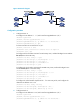
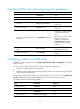
R2 signaling configuration example
Network requirements
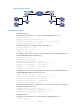
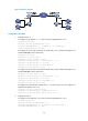
As shown in Figure 20, configure R2 signaling on the routers so the telephones can call each other.