
R0106-HP MSR Router Series Voice Configuration Guide(V7)
47
[RouterB-GigabitEthernet1/0/1] quit
# Create a timeslot set on interface E1 2/4/1.
[RouterB] controller e1 2/4/1
[RouterB-E1 2/4/1] timeslot-set 1 timeslot-list 1-31 signal r2
[RouterB-E1 2/4/1] quit
# Configure the local number 07552001 for POTS entity 2001, and bind the digital voice
interfaces line 2/4/1:1 to the POTS entity.
[RouterB] voice-setup
[RouterB-voice] dial-program
[RouterB-voice-dial] entity 2001 pots
[RouterB-voice-dial-entity2001] match-template 07552001
[RouterB-voice-dial-entity2001] line 2/4/1:1
[RouterB-voice-dial-entity2001] send-number all
[RouterB-voice-dial-entity2001] quit
# Configure the local number 07552002 for POTS entity 2002, and bind the digital voice
interfaces line 2/4/1:1 to the POTS entity.
[RouterB-voice-dial] entity 2002 pots
[RouterB-voice-dial-entity2002] match-template 07552002
[RouterB-voice-dial-entity2002] line 2/4/1:1
[RouterB-voice-dial-entity2002] send-number all
[RouterB-voice-dial-entity2002] quit
# Configure the called number template 010…. for VoIP entity 010, and configure the destination
IP address as 1.1.1.1.
[RouterB-voice-dial] entity 010 voip
[RouterB-voice-dial-entity10] match-template 010....
[RouterB-voice-dial-entity10] address ip 1.1.1.1
Verifying the configuration
# Place a call from a telephone attached to Router A to a telephone attached to Router B to verify that the
telephones can call each other through R2 signaling.
# Use the display voice subscriber-line command to display information about digital voice interfaces.
(Details not shown.)
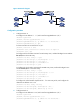
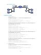
E1 DSS1 signaling configuration example
Network requirements
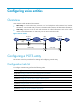
As shown in Figure 21, the routers connect to the PBXs through E1 interfaces.
Configure DSS1 signaling on the routers so the telephones can call each other.