
R0106-HP MSR Router Series Security Configuration Guide(V7)


399
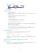
Figure 117 Network diagram
Configuration procedure
1. Configure the DHCP server.
For information about DHCP server configuration, see Layer 3—IP Services Configuration Guide.
2. Configure the device:
# Configure IP addresses for the interfaces. (Details not shown.)
# Enable DHCP snooping.
<Device> system-view
[Device] dhcp snooping enable
# Configure GigabitEthernet 2/1/2 as a trusted interface.
[Device] interface gigabitethernet 2/1/2
[Device-GigabitEthernet2/1/2] dhcp snooping trust
[Device-GigabitEthernet2/1/2] quit
# Enable IPv4 source guard on GigabitEthernet 2/1/1 and verify the source IP address and MAC
address for dynamic IP source guard.
[Device] interface gigabitethernet 2/1/1
[Device-GigabitEthernet2/1/1] ip verify source ip-address mac-address
# Enable recording of client information in DHCP snooping entries on GigabitEthernet 2/1/1.
[Device-GigabitEthernet2/1/1] dhcp snooping binding record
[Device-GigabitEthernet2/1/1] quit
Verifying the configuration
# Display dynamic IPv4 source guard binding entries obtained from DHCP snooping.
[Device] display ip source binding dhcp-snooping
Total entries found: 1
IP Address MAC Address Interface VLAN Type
192.168.0.1 0001-0203-0406 GE2/1/1 1 DHCP snooping
The output shows that a dynamic IPv4 source guard binding entry is generated based on a DHCP
snooping entry.
Static IPv6 source guard configuration example
Network requirements
As shown in Figure 118, configure a static IPv6 source guard binding entry on GigabitEthernet 2/1/1 of
the device to allow only IPv6 packets from the host to pass.