
R0106-HP MSR Router Series Security Configuration Guide(V7)

408
Ste
p
Command
Remarks
2. Enter Layer 3 Ethernet interface,
Layer 3 Ethernet subinterface, Layer 3
aggregate interface, or Layer 3
aggregate subinterface view.
interface interface-type
interface-number
N/A
3. Enable authorized ARP on the
interface.
arp authorized enable
By default, authorized ARP is
disabled.
Configuration example (on a DHCP server)
Network requirements
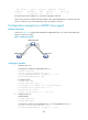
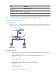
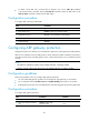
As shown in Figure 122, configure authorized ARP on GigabitEthernet 2/1/1 of Device A (a DHCP
server) to ensure user validity.
Figure 122 Network diagram
Configuration procedure
1. Configure Device A:
# Specify the IP address for GigabitEthernet 2/1/1.
<DeviceA> system-view
[DeviceA] interface gigabitethernet 2/1/1
[DeviceA-GigabitEthernet2/1/1] ip address 10.1.1.1 24
[DeviceA-GigabitEthernet2/1/1] quit
# Configure DHCP.
[DeviceA] dhcp enable
[DeviceA] dhcp server ip-pool 1
[DeviceA-dhcp-pool-1] network 10.1.1.0 mask 255.255.255.0
[DeviceA-dhcp-pool-1] quit
# Enter Layer 3 Ethernet interface view.
[DeviceA] interface gigabitethernet 2/1/1
# Enable authorized ARP.
[DeviceA-GigabitEthernet2/1/1] arp authorized enable
[DeviceA-GigabitEthernet2/1/1] quit
2. Configure Device B:
<DeviceB> system-view
[DeviceB] interface gigabitethernet 2/1/1
[DeviceB-GigabitEthernet2/1/1] ip address dhcp-alloc
[DeviceB-GigabitEthernet2/1/1] quit
Verifying the configuration
# Display authorized ARP entry information on Device A.
[DeviceA] display arp all