
R0106-HP MSR Router Series Security Configuration Guide(V7)


419
NOTE:
• This feature is available on only the routers installed with Layer 2 switching modules.
• The term "switch" in this section refers to the router installed with Layer 2 switching modules.
Configuration guidelines
Follow these guidelines when you configure ARP filtering:
• You can configure a maximum of eight permitted entries on an interface.
• Do not configure both the arp filter source and arp filter binding commands on an interface.
• If ARP filtering works with ARP detection, ARP filtering applies first.
Configuration procedure
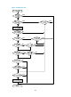
To configure ARP filtering:
Ste
p
Command
Remarks
1. Enter system view.
system-view N/A
2. Enter Layer 2 Ethernet interface
view.
interface interface-type interface-number
N/A
3. Enable ARP filtering and
configure a permitted entry.
arp filter binding ip-address
mac-address
By default, ARP filtering is
disabled.
Configuration example
Network requirements
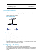
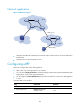
As shown in Figure 127, the IP and MAC addresses of Host A are 10.1.1.2 and 000f-e349-1233,
respectively. The IP and MAC addresses of Host B are 10.1.1.3 and 000f-e349-1234, respectively.
Configure ARP filtering on GigabitEthernet 2/1/1 and GigabitEthernet 2/1/2 of Switch B to permit ARP
packets from the two hosts only.