HP MSR4000 Routers Installation Guide Part number: 5998-3980 Document version: 6W102-20140607
Legal and notice information © Copyright 2014 Hewlett-Packard Development Company, L.P. No part of this documentation may be reproduced or transmitted in any form or by any means without prior written consent of Hewlett-Packard Development Company, L.P. The information contained herein is subject to change without notice.
Contents Legal and notice information·········································································································································i Preparing for installation ············································································································································· 1 Safety recommendations ··············································································································································
Replacing a MIM ··························································································································································· 48 Troubleshooting ·························································································································································· 49 Troubleshooting the power supply system failure ······································································································· 49 Trouble
Preparing for installation The HP MSR4000 Router Series includes the models in Table 1.
• Do not open or close the chassis cover when the router is powered on. • Correctly connect the interface cables of the router. • Use an uninterrupted power supply (UPS). • If there are two power inputs, disconnect the two power inputs to power off the router. • Do not work alone when the router has power. • Always make sure the power has been disconnected during the installation and replacement procedures. Laser safety • Do not stare into any fiber port when the router has power.
Substance Concentration limit (particles/m3) NOTE: Dust particle diameter ≥ 5 μm The equipment room must also meet strict limits on salts, acids, and sulfides to eliminate corrosion and premature aging of components, as shown in Table 4. Table 4 Harmful gas limits in the equipment room Gas Max. (mg/m3) SO2 0.2 H2S 0.006 NH3 0.05 Cl2 0.01 Cooling system The MSR4000 router adopts left to rear airflow for heat dissipation.
ESD prevention CAUTION: Check the resistance of the ESD wrist strap for safety. The resistance reading should be in the range of 1 to 10 megohm (Mohm) between human body and the ground. To prevent electrostatic discharge (ESD), follow these guidelines: • Make sure the router and the floor are well grounded. • Take dust-proof measures for the equipment room. • Maintain the humidity and temperature at an acceptable level.
• Install a special lightning arrester at the input end of outdoor signal lines (for example, E1/T1 line) to which interface modules of the router are connected to enhance the lightning protection capability. Rack-mounting Before mounting the router in a rack, adhere to the following requirements: • The rack is equipped with a good ventilation system. • The rack is sturdy enough to support the router and its accessories.
Item Requirements Temperature 0°C to 45°C (32°F to 113°F). Relative humidity 5% to 90% (noncondensing). Cleanness • Dust concentration ≤ 3 × 10⁴ particles/m3. • No visible dust on desk within three days. • The equipment and floor are well grounded. • The equipment room is dust-proof. • The humidity and temperature are at an acceptable level, respectively. • Wear an ESD wrist strap and uniform when ESD prevention touching a circuit board.
Item Requirements Tools • Installation accessories supplied with the router. • User supplied tools. Reference • Documents shipped with the router. • Online documents.
Installing the router WARNING! To avoid injury, do not touch bare wires, terminals, or parts with high-voltage hazard signs. IMPORTANT: • The barcode on the router chassis contains product information that must be provided to local sales agent before you return a faulty router for service. • Keep the tamper-proof seal on a mounting screw on the chassis cover intact, and if you want to open the chassis, contact HP for permission. Otherwise, HP shall not be liable for any consequence.
Figure 2 Installation flowchart Start Install an air filter Mount the router to a workbench Mount to a specific position? Mount the router to a rack Examine the workbench Mount the router to a rack Ground the router Install an MPU Install an SPU Install a CF card Install an interface module Install a power supply Connect interface cables Connect a power cord Verifying the installation Troubleshoot the router Power on the router Operating correctly? Yes End 9 No Power off the router
Installing the router Installing an air filter No air filter is provided with the router. Purchase one yourself. To install an air filter: 1. Face the left side (side of the inlet vents) of the router. 2. Install the upper and lower guide rails of the air filter to the chassis. See Figure 3. Figure 3 Installing the upper and lower guide rails 3. Push the air filter along the slide rails from the rear side of the chassis to the front. 4. Fasten the captive screws on the air filter.
Mounting the router on a workbench IMPORTANT: • Ensure good ventilation and 10 cm (3.94 in) of clearance around the chassis for heat dissipation. • Avoid placing heavy objects on the router. To mount the router on a workbench: 1. Make sure the workbench is clean, stable, and correctly grounded. 2. Place the router on the workbench with the upside up.
Figure 7 MSR4080 mounting brackets Rack-mounting clearance requirements Figure 8 Rack-mounting clearances Front mounting bracket Power cord E1 cable 60mm 480mm 60mm 12
Table 6 Rack-mounting clearance requirements Model 4060 Router dimensions Rack clearance requirements • Width—440 mm (17.32 in) • Height—175.1 mm (6.89 in) (4 RU) • Total depth—600 mm (23.62 in) The rack must meet the following requirements: { { { 480 mm (18.90 in) for the chassis • At least 80 mm (3.15 in) between the front 60 mm (2.36 in) for connecting an E1 cable at the front of the chassis • At least 550 mm (21.65 in) between the 60 mm (2.
Figure 9 Installing a cage nut 1 2 3. Install other cage nuts to all the marked positions on the rack posts. 4. Install a rack shelf at the position where the cage nuts are installed.
Figure 10 Installing a rack shelf 5. Attach the front mounting brackets to the chassis and fasten the screws clockwise.
Figure 11 Attaching the front mounting brackets to the MSR4060 Figure 12 Attaching the front mounting brackets to the MSR4080 16
6. Place the router on the rack shelf, and secure the chassis by attaching the front mounting brackets with pan head screws to the rack. The specifications of pan head screws must satisfy the installation requirements, and rustproof treatment has been made to their surfaces. Figure 13 shows installing an MSR4060 router to the rack. Install other MSR4000 routers in the same way.
Grounding the router through the grounding terminal on the rack IMPORTANT: Make sure the rack is correctly grounded before grounding the router. To connect the grounding cable: 1. Remove the two grounding screws from the rear panel of the chassis. 2. Attach the grounding screws to the ring terminal of the grounding cable. 3. Use a Phillips screwdriver to fasten the grounding screws into the grounding screw holes. 4. Remove the grounding screw from the grounding point on the rack. 5.
Grounding the router with a grounding strip If a grounding strip is available at the installation site, use grounding screws to attach the ring terminal of the grounding cable to the grounding strip, and make sure the grounding strip is correctly grounded.
Figure 15 Grounding the router with a grounding strip Grounding the router with a grounding conductor buried in the earth ground If the installation site has no grounding strips, but earth ground is available, hammer a 0.5 m (1.64 ft) or longer angle iron or steel tube into the earth ground to serve as a grounding conductor. The steel tube must be zinc-coated. Weld the yellow-green grounding cable to the angel iron or steel tube and treat the joint for corrosion protection.
Figure 16 Installing the MPU-100 Installing an SPU CAUTION: SPUs are not hot swappable. Make sure the router is powered off before installing an SPU. MSR4000 routers support the SPU-100, SPU-200, and SPU-300. The installation procedures are similar. This section describes installation of an SPU-200 to the MSR4060. To install an SPU: 1. Insert the SPU into the slot along the guide rails, and push the ejector levers inward. 2.
Installing a CF card 1. Open the CF card cover by pressing the spring clip. 2. Push the CF card eject button all the way into the slot, and make sure the button does not project from the panel. 3. Insert the CF card into the slot following the direction shown in Figure 18, and make sure it does not project from the slot. 4. Close the CF card cover. Figure 18 Installing a CF card Installing an interface module An HMIM or MIM interface module can be 1U or 0.5U. This section takes a 0.
2. Push the HMIM slowly along the slide rails into the slot until it makes close contact with the backplane of the router. 3. Fasten the captive screws on the HMIM to secure it to the router. Figure 19 Installing an HMIM Installing a MIM IMPORTANT: • To install a MIM, install it to the HMIM adapter and then insert it into the HMIM slot. • You can install a MIM when the router is powered on.
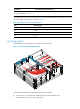
Figure 21 Installing the MIM to the router Installing a power supply IMPORTANT: • To install multiple power supplies, make sure all power supplies are AC input or DC input. • Power supplies are hot swappable. Installing an AC/DC power supply 1. Face the front of the router and locate the slot to be used. 2. Loosen the captive screws with a Phillips screwdriver to remove the filler panel from the slot. Keep the removed filler panel for future use.
Figure 22 Installing an AC power supply Figure 23 Installing a DC power supply Installing a PoE power supply 1. Face the front of the router and locate the slot to be used. 2. Loosen the captive screws with a Phillips screwdriver to remove the filler panel from the slot. Keep the removed filler panel for future use. Skip this step if the PoE power supply slot does not have a filler panel when the router is shipped.
Figure 24 Removing the filler panel 3. Holding the handle of the power supply with one hand and supporting the bottom of the power supply with the other hand, insert the power supply slowly along the slide rails until it makes close contact with the backplane. Figure 25 Installing a PoE power supply 4. Use a Phillips screwdriver to fasten the captive screws on the two sides of the power supply. Connecting the router to the network Connect the router to the network before powering on the router.
Figure 26 Connecting the router to a PC Connecting an optical fiber WARNING! Do not stare into any fiber port when you connect an optical fiber. The laser light emitted from the optical fiber might hurt your eyes. Follow these guidelines when you connect a fiber cable: • Never bend or curve a fiber when connecting it. • Make sure the Tx and Rx ends are correctly connected. • Keep the fiber end clean. • Be sure to install the dust cover if the fiber port is not connected to a fiber connector.
Figure 27 Connecting an optical fiber Connecting the power cord The power cords in the figures of this section are only for illustration. Connecting an AC power cord 1. Make sure the router is well grounded, and the power switch on the router is in the OFF position. 2. Connect one end of the AC power cord to the AC receptacle on the router, and use a cable tie to secure the power cord. 3. Connect the other end of the power cord to the AC power source.
Figure 28 Connecting an AC power cord to the router Connecting a DC power cord WARNING! Pay attention to the mark on a power cord to avoid connection errors. To connect DC power cords: 1. Make sure the router is well grounded, and the power switch on the router is in the OFF position. 2. Loosen the captive screws on the power supply with a Phillips screwdriver to remove the power supply connector. 3.
Figure 29 Connecting a DC power cord for the router Verifying the installation After you complete the installation, verify that: • There is enough space for heat dissipation around the router, and the rack or workbench is stable. • USB devices and interface modules are correctly installed. • The router, rack, and power cords are correctly grounded. • The correct power source is used.
Figure 30 Connecting the console cable IMPORTANT: Download and install the USB console driver program before configuring the device when you connect the device through a USB console cable. To connect a USB cable: 3. Connect the USB port to the PC. 4. Connect the other end to the USB console port of the router.
Figure 31 Connecting the USB cable 5. Click the following link, or copy it to the address bar on the browser to log in to download page of the USB console driver, and download the driver. http://www.exar.com/connectivity/uart-and-bridging-solutions/usb-uarts/xr21v1410 6. Select a driver program according to the operating system you use: { { 7. XR21V1410_XR21B1411_Windows_Ver1840_x86_Installer.EXE—Applicable to 32-bit operating systems. XR21V1410_XR21B1411_Windows_Ver1840_x64_Installer.
Figure 32 Device driver installation wizard 8. Click Continue Anyway if the following dialog box appears. 9. Click Finish.
Figure 33 Completing the device driver installation wizard Setting terminal parameters This section uses a PC with Windows XP as an example. To set terminal parameters: 1. Select Start > All Programs > Accessories > Communications > HyperTerminal. The Connection Description dialog box appears. Figure 34 Connection description 2. Select the serial port to be used from the Connect using list, and click OK.
Figure 35 Setting the serial port used by the HyperTerminal connection 3. Set Bits per second to 9600, Data bits to 8, Parity to None, Stop bits to 1, and Flow control to None, and click OK. Figure 36 Setting the serial port parameters 4. Select File > Properties in the HyperTerminal window.
Figure 37 HyperTerminal window 5. On the Settings tab, set the emulation to VT100 or Auto detect and click OK. Figure 38 Setting terminal emulation in test Properties dialog box Powering on the router 1. Turn on the switch of the power supply system for the router.
2. Turn on the switch of the AC or DC power supplies. Displaying boot information Power on the router, and you can see the following information: System is starting... Press Ctrl+D to access BASIC-BOOTWARE MENU... Press Ctrl+T to start heavy memory test Booting Normal Extended BootWare........ The Extended BootWare is self-decompressing....Done. **************************************************************************** * * * HP MSR4060 BootWare, Version 1.
Line con1 is available. Press ENTER to get started. Press Enter, and the following prompt appears: You can now configure the router. Examining the router after power-on After the router is powered on, verify that: • The LEDs on the MPU are operating correctly: • The configuration terminal displays information correctly. For local configuration, the configuration terminal displays the boot information (see "Displaying boot information").
Replacement procedure IMPORTANT: • The barcode on the router chassis contains product information that must be provided to local sales agent before you return a faulty router for service. • Keep the tamper-proof seal on a mounting screw on the chassis cover intact, and if you want to open the chassis, contact HP for permission. Otherwise, HP shall not be liable for any consequence. Replacing a power supply Power supplies are hot swappable.
Replacing a fan tray 1. Face the rear panel of the router. 2. Use a Phillips screwdriver to loosen the captive screws of the fan tray. 3. Holding the handle of the fan tray with one hand and supporting the bottom of the fan tray with the other hand, gently pull the fan tray out of the slot along the slide rails. Figure 40 Removing a fan tray 4.
Figure 41 Removing the SPU-200 Replacing an MPU MPUs are hot swappable. To replace an MPU-100: 1. Use a Phillips screwdriver to loosen the captive screws of the MPU until the spring pressure is released. 2. Pivot the ejector levers of the MPU outward, and gently pull the MPU out of the slot. 3. Install a new MPU. For the installation procedure, see "Installing the router.
Replacing a VPM NOTE: Before you replace a VPM, remove the SPU from the chassis. For information about removing an SPU, see "Replacing an SPU." VPM (Voice Processing Module) functions to implement the encryption/decryption, EC and CNG of voices.
5. Verify that the release latches have firmly locked the VPM in position. Figure 45 Removing a VPM Figure 46 Installing a VPM 1 2 Replacing a memory module NOTE: Before you replace a memory module, remove the MPU from the chassis. For information about removing the MPU, see "Replacing an MPU.
Figure 47 MPU structure 1 2 (1) Front panel (2) Memory module To replace a memory module: 1. Pull the release latches away from the memory module at both ends so that the memory module springs up from the slot. 2. Holding the non-conductive edge, remove the memory module. Keep the removed memory module for future use. 3. Align the polarization notch of a new memory module with the memory module slot on the main board and insert the memory module into the slot along the slide rails. 4.
Figure 49 Installing a memory module 1 2 Replacing an air filter 1. Use a Phillips screwdriver to completely loosen the captive screws of the air filter. 2. Gently pull the air filter out along the slide rails. Figure 50 Removing an air filter 3. Install a new air filter. For the installation procedure, see "Installing the router." To remove the slide rails, completely loosen the fastening screws of the slide rails. To install new slide rails, see "Installing the router.
Figure 51 Removing slide rails Replacing a CF card CAUTION: Execute the umount cfb0: command before you remove the CF card if the router is powered on. To replace a CF card: 1. Press down the spring clip of the CF card cover and open the cover. 2. Press the CF card eject button of the CF card reader so that the eject button projects from the panel. 3. Press the eject button again to eject the CF card part-way out of the CF card reader, and then pull the CF card out of the CF card reader.
Figure 52 Removing a CF card Replacing an HMIM WARNING! Before replacing an HMIM when the router is powered on, you must execute the remove hmimslot slotnumber command first. 1. Completely loosen the captive screws of the HMIM. 2. Gently pull the HMIM out of the slot along the slide rails. 3. Install a new HMIM. For the installation procedure, see "Installing the router." If you do not install a new HMIM, install a filler panel and tighten the screws.
Replacing a MIM WARNING! Before replacing a MIM when the router is powered on, you must execute the remove hmimslot slotnumber command first. To replace a MIM: 1. Completely loosen the captive screws of the HMIM adapter. 2. Gently pull the MIM and the HMIM adapter out of the slot along the slide rails. Figure 54 Removing a MIM and the HMIM adapter 3.
Troubleshooting IMPORTANT: • The barcode on the router chassis contains product information that must be provided to local sales agent before you return a faulty router for service. • Keep the tamper-proof seal on a mounting screw on the chassis cover intact, and if you want to open the chassis, contact HP for permission. Otherwise, HP shall not be liable for any consequence. Troubleshooting the power supply system failure Symptom The router cannot be powered on. The power LED is off.
Troubleshooting the configuration system failures If the router operates correctly after being powered on, the boot information is displayed on the configuration terminal. If the configuration system is faulty, the configuration terminal displays garbled characters or does not display anything. No display on the configuration terminal Symptom After the router is powered on, the console terminal does not display anything.
Troubleshooting interface module, cable, and connection failure Symptom After an interface module is installed and the router is powered on, the LEDs on the interface module panel indicate that the interface module is operating incorrectly. Solution To resolve the problem: 1. Verify that the interface module makes good contact with the rear panel of the router slot. 2. Verify that the router supports the interface module. 3. Verify that the interface module is installed in the specified router slot.
Scenario 3 Symptom The router crashes. Solution Press the Reset button for a short time to reboot the router. Reset button usage guidelines An MSR4000 router provides the Reset button. You can use the button to reboot the system or restore the factory settings. 1. Press the Reset button for a short time to reboot the router. 2. Press the Reset button for more than 4 seconds to reboot the router and restore the factory settings.
Appendix A Chassis views and technical specifications Chassis views The router appearance in this installation guide is for illustration only.
(4) Power supply slot PWR2 (5) Power supply slot PWR3 (6) Power supply slot PWR1 (7) Filler panels of the PoE power supply slots MSR4080 Figure 58 Front view 4 6 5 3 2 1 7 8 9 10 11 (1) MPU slot 0 (2) SPU slot (3) MPU slot 1 (4) HMIM slot 8 (5) HMIM slot 6 (6) HMIM slot 4 (7) HMIM slot 2 (8) HMIM slot 7 (9) HMIM slot 5 (10) HMIM slot 3 (11) HMIM slot 1 Figure 59 Rear view 2 1 7 3 4 5 6 (1) Fan tray (2) Grounding terminal (3) Power supply slot PWR 4 (4) Power supply slot
MPU MPU-100 is required for the MSR4000, which performs protocol processing, low-speed packet forwarding, interface control, and fault detection. The MPU runs system programs and saves configuration information of the router.
(3) USB port 1 (4) Copper Ethernet ports GE0 to GE3 (5) 10 G SFP+ port (6) USB port 0 SPU-300 Figure 63 Rear view (1) Captive screw (2) Fiber Ethernet ports SFP0 to SFP3 (3) USB port 1 (4) Copper Ethernet ports GE0 to GE3 (5) 10 G SFP+ port (6) USB port 0 Power supplies IMPORTANT: • To install multiple power supplies, make sure all power supplies are AC input or DC input.
3 ≤4 ≤2 2 ≤6 ≤4 1 ≤8 ≤6 0 ≤ 10 ≤8 If the quantities of A-type and B-type modules do not meet the requirements, two power supplies are required.
PoE power supply Figure 66 PoE power supply (1) Captive screw (2) Power switch (3) Air outlet vent (4) Power receptacle Technical specifications Table 8 Technical specifications Item MSR4060 MSR4080 MPU slot 2 2 SPU slot 1 1 HMIM slot 6 8 Dimensions (H × W × D), excluding rubber feet and mounting brackets 175.1 × 440 × 480 mm (6.89 × 17.32 × 18.90 in) 219.5 × 440 × 480 mm (8.64 × 17.32 × 18.
Rated power 300 W Table 11 PoE power supply specifications Item Specification Model PSR750-A Rated input voltage range 100 VAC to 240 VAC @ 50 Hz or 60 Hz 300 W to the system Rated power 450 W to PDs Table 12 MPU-100/MPU-100 TAA specifications Item Specification Console port 1 AUX port 1 GE management port 1 USB console port 1 USB port 1 Memory • 2 GB DDR3 (default) • 4 GB DDR3 (maximum) CF card • 512 MB (default) • 4 GB (maximum) CF card slot 1 Flash 8 MB Table 13 SPU specific
Appendix B LEDs Panel LEDs Appearance Figure 67 MPU-100/MPU-100 TAA LEDs (1) CF card LED (2) USB console port LED (3) Console port LED (4) System LED (SYS) (5) Power supply LED (PWR) (6) PoE power supply LED (7) MPU status LED (ACT) (8) Fan LED (FAN) Figure 68 SPU-100 LEDs (1) SFP port LED (2) GE port LED (4) VPM0 slot status LED (5) VPM1 slot status LED (3) SPU status LED (RUN) Figure 69 SPU-200 LEDs (1) SFP port LED (2) GE port LED (3) 10 G SFP+ port LED (4) SPU status LED (RUN) (5) VP
Figure 70 SPU-300 LEDs (1) SFP port LED (2) GE port LED (3) 10 G SFP+ port LED (4) SPU status LED (RUN) (5) VPM0 slot status LED (6) VPM1 slot status LED Description Table 14 LED description LED CF card LED Location MPU-100 USB console port LED MPU-100 Console port LED MPU-100 System LED (SYS) Power supply LED (PWR) MPU-100 MPU-100 Status Description Steady green A CF card is in position and the host has detected the CF card.
LED PoE power supply LED MPU status LED (ACT) Fan LED (FAN) SFP port LED GE port LED SPU status LED (RUN) VPM0 slot status LED VPM1 slot status LED 10 G SFP+ port LED Location MPU-100 MPU-100 MPU-100 SPU SPU SPU SPU SPU SPU-200/SP Status Description Off No PoE power supply is installed or the PoE power supply is faulty. Steady green The PoE power supply is operating correctly. Steady yellow The PoE power supply is faulty. Off The MPU is in standby state.
LED Location Status Description U-300 Steady green An SFP link is present. Flashing green Data is being sent or received on the SFP link. Steady yellow The transceiver module has failed to pass the detection on the 10 G SFP+ port or the transceiver module cannot be identified.
Figure 73 PoE power supply LEDs 1 (1) Power input LED 2 (2) Power output LED Description Table 15 LED description LED Location AC OK AC power supply DC OK AC power supply Input DC power supply Output DC power supply AC OK PoE power supply DC OK PoE power supply Status Description Off No power input or the power input is faulty. Steady green The power is input correctly. Off No power output or the power output is faulty. Steady green The power is output correctly.
Appendix C Slot arrangement Table 16 Slot arrangement Model Slot arrangement MSR4060 MSR4080 MPU slots SPU slots HMIM slots 65
Support and other resources Contacting HP For worldwide technical support information, see the HP support website: http://www.hp.
Conventions This section describes the conventions used in this documentation set. Command conventions Convention Description Boldface Bold text represents commands and keywords that you enter literally as shown. Italic Italic text represents arguments that you replace with actual values. [] Square brackets enclose syntax choices (keywords or arguments) that are optional. { x | y | ... } Braces enclose a set of required syntax choices separated by vertical bars, from which you select one.
Network topology icons Represents a generic network device, such as a router, switch, or firewall. Represents a routing-capable device, such as a router or Layer 3 switch. Represents a generic switch, such as a Layer 2 or Layer 3 switch, or a router that supports Layer 2 forwarding and other Layer 2 features. Represents an access controller, a unified wired-WLAN module, or the switching engine on a unified wired-WLAN switch. Represents an access point. Represents a mesh access point.
Index ACDEGILMNPRSTVW A Logging in through the console port,30 AC power supply,57 M Appearance,63 Mounting the router on a workbench,11 Appearance,60 Mounting the router to a rack,11 C MSR4060,53 MSR4080,54 Cleanness,2 Configuring basic settings for the router,38 N Connecting the power cord,28 No display on the configuration terminal,50 Connecting the router to the network,26 No response from the serial port,50 Cooling system,3 P D PoE power supply,58 DC power supply,57 Powering on the