
HP MSR4000 Router Series Installation Guide


13
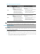
Table 6 Rack-mounting clearance requirements
Model Router dimensions
Rack clearance re
q
uirements
4060
• Width—440 mm (17.32 in)
• Height—175.1 mm (6.89 in) (4 RU)
• Total depth—600 mm (23.62 in)
{ 480 mm (18.90 in) for the chassis
{ 60 mm (2.36 in) for connecting an E1
cable at the front of the chassis
{ 60 mm (2.36 in) for connecting a
power cord at the rear of the chassis
The rack must meet the following
requirements:
• At least 80 mm (3.15 in) between the front
rack post and the front door.
• At least 550 mm (21.65 in) between the
front rack post and the rear door.
4080
• Width—440 mm (17.32 in)
• Height—219.5 mm (8.64 in) (5 RU)
• Total depth—600 mm (23.62 in)
{ 480 mm (18.90 in) for the chassis
{ 60 mm (2.36 in) for connecting an E1
cable at the front of the chassis
{ 60 mm (2.36 in) for connecting a
power cord at the rear of the chassis
The rack must meet the following
requirements:
• At least 80 mm (3.15 in) between the front
rack post and the front door.
• At least 550 mm (21.65 in) between the
front rack post and the rear door.
IMPORTANT:
HP recommends that you use a rack shelf and a rack with a depth of more than 0.68 m (2.23 ft).
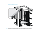
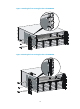
Installing the router to the rack
CAUTION:
The mounting brackets and rack shelf can support only the weight of the router. Do not place any objec
t
on the router to avoid device damage.
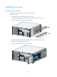
To install the router to the rack:
1. Use a front mounting bracket to mark the positions of cage nuts, making sure they are at the same
level.
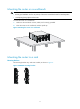
2. Insert one edge of a cage nut into the hole. Use a flat-blade screwdriver to compress the other edge
of the cage nut, and then push the cage nut fully into the hole.