
HP MSR4000 Router Series Installation Guide


56
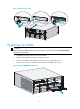
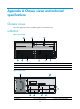
(3) USB port 1 (4) Copper Ethernet ports GE0 to GE3
(5) 10 G SFP+ port (6) USB port 0
SPU-300
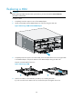
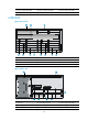
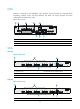
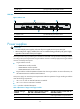
Figure 63 Rear view
(1) Captive screw (2) Fiber Ethernet ports SFP0 to SFP3
(3) USB port 1 (4) Copper Ethernet ports GE0 to GE3
(5) 10 G SFP+ port
(6) USB port
0
Power supplies
IMPORTANT:
• To install multiple power supplies, make sure all power supplies are AC input or DC input.
• When a PoE power supply is installed, the router is considered being powered by only power supply
regardless of the number of the power supplies.
Power requirements vary by module types. Modules are classified as A-type modules and B-type modules
according to the power requirements. A-type modules consume a relatively high power. B-type modules
consume a relatively small power.
• A-type modules include:
{ HMIM-16FXS interface module
{ HMIM-24GSW interface module
{ HMIM-24GSW-POE interface module
• B-type modules include the HMIMs and VPMs other than A-type modules. For more information, see
HP MSR Series Routers Interface Module Manual.
One power supply can meet the power requirements when the quantities of A-type and B-type modules
meet the following requirements:
• 2A + B ≤ 10 when an SPU-100\SPU-200 is installed.
• 2A + B ≤ 8 when an SPU-300 is installed.
Table 7 pr
ovides a detailed description.
Table 7 Quantities of A-type and B-type modules
Quantity of A-type
modules
Quantity of B-type modules with an
SPU-100 or SPU-200 installed
Quantity of B-type modules with an
SPU-300 installed
5 0 One A-type module is not powered on.
4 ≤ 2 0