
HP B-series 16Gb FC Switches Quick Start Instructiions
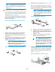
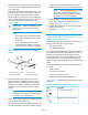
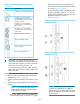
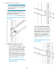
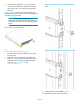
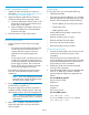
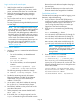

Table 1 SAN Switch Rack Mount Kit hardware
(continued)
DescriptionItem
A left inner rail and a left outer rail
14 #8-32 x 5/16-inch Phillips
panhead SEMS screws for use with
the SN6500B Switch. This device
requires 10 screws
14 #8-32 x 3/16-inch Phillips
panhead screws with thread lock
(do not use)
Ten #10-32 x 1/2-inch Phillips
panhead screws with captive star
lock washers
Eight #10 alignment washers
Eight #10 adapter washers
Two 1/4-20 hex nuts with captive
star lock washers
Two 1/4-inch flat washers
CAUTION: For proper air flow, the SFP+
media side of the device port side must face the
rear of the rack. This allows cool air to enter the
front of the rack and exit from the rear.
For switches with Port Side Air Intake, the SFP+
media side of the device port side must face the
front of the rack.
To install the device in a rack:
1. Verify that the required parts and hardware are
available (see Table 1 (page 5)).
2. Choose a mounting location for the device in the
rack.
3. Attach the rear mounting brackets to the rear rack
uprights.
NOTE: For switches with Port Side Air
Intake, attach the rear mounting brackets
to the front rack uprights.
• For an HP 10000 series rack, assemble each
of the brackets using two #10-32 x 1/2-inch
Phillips panhead screws with captive star
lock washers and two #10 adapter washers,
as shown in Figure 9 (page 6).
• For an HP System/e Rack, install the two rear
mounting brackets using 8-32 x 5/16-inch
Phillips panhead SEMS screws and two #10
alignment washers, as shown in
Figure 10 (page 6).
Figure 9 Installing the rear mounting brackets (HP
10000 Series Rack)
Figure 10 Installing the rear mounting brackets
(HP System/e Rack)
NOTE: The SAN Switch Rack Mount Kit
contains rails labeled Left and Right to
designate the left side and right side of the
device or cabinet as viewed from the front
of the cabinet.
Page 6