
HP B-series 16Gb FC Switches Quick Start Instructiions
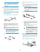

5. Use the screw type #8-32 x 5/16-inch (in the
screw holes marked 16) to attach the two inner
rails to the switch. Five screws are required for
each rail.
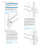
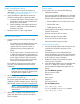
Figure 14 (page 8) shows how the inner rails are
attached to the switch with the open ends (highlighted
in yellow) on the port side.
NOTE: The switch in the figure is not a
SN6500B, but it shows the direction of the open
ends of the rails when they are attached to the
switch.
Figure 14 Inner rails attachment
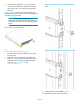
Securing the device to the outer rails
1. Insert the device with the attached inner rails to
the outer rails.
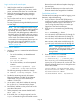
2. Insert the device into the rack and install one
#10-32 x 1/2-inch Phillips panhead screw with
captive star lock washer. Repeat for the other
side. See Figure 15 (page 8) and
Figure 16 (page 8).
Figure 15 Securing the device (HP 10000 Series
Rack)
Figure 16 Securing the device (HP System/e Rack)
3. Tighten the hex nuts installed in Step 4.
This completes the rack mount procedure.
Page 8