HP DC SAN Backbone Director Switch Hardware Reference Guide Abstract This document provides information about setting up, configuring, and maintaining the HP DC SAN Backbone Director Switch (DC SAN Director). It is intended for system administrators and technicians with knowledge of SANs and DC SAN Directors.
© Copyright 2008-2012 Hewlett-Packard Development Company, L.P. © Copyright 2008-2012 Brocade Communications Systems, Incorporated The information contained herein is subject to change without notice. The only warranties for HP products and services are set forth in the express warranty statements accompanying such products and services. Nothing herein should be construed as constituting an additional warranty. HP shall not be liable for technical or editorial errors or omissions contained herein.
Contents 1 DC SAN Director overview..........................................................................7 Power Pack..............................................................................................................................7 Features..................................................................................................................................7 Hardware components .......................................................................................................
5 Replacing DC SAN Director FRUs...............................................................62 Replacing the chassis door......................................................................................................62 Removing the chassis door..................................................................................................62 Installing the chassis door...................................................................................................
Related information.................................................................................................................96 HP websites......................................................................................................................96 Rack stability.....................................................................................................................97 Typographic conventions........................................................................................
Korean notices............................................................................................................118 Environmental regulation compliance......................................................................................119 China RoHS....................................................................................................................119 Environmental Protection Use Period (EPUP) Disclaimer.....................................................
1 DC SAN Director overview This chapter provides an overview of the DC SAN Director. Power Pack The DC SAN Director Power Pack model (part numbers AK857A, AK857B, and AK857C) represents the next generation of advanced Fibre Channel (FC) enterprise-class platforms used to intelligently interconnect storage devices, hosts, and servers in a SAN. The DC SAN Director is the highest-performance and highest-scalability enterprise-class product offered by HP.
Hardware components The DC SAN Director features a modular and scalable mechanical construction that allows a wide range of flexibility in installation, fabric design, and maintenance. The chassis can be mounted with the cables facing the front of the equipment rack or to the rear, and consists of the following: • Up to eight hot-swappable Director blade assemblies can be configured in a single chassis, delivering up to 512 FC ports.
◦ 4-Gb and 8-Gb SFP optical transceivers (4-Gb SFPs operate at 1 Gb, 2 Gb, or 4 Gb. 8-Gb SFPs operate at 2 Gb, 4 Gb, or 8 Gb.) ◦ XFP optical transceivers (10-Gb/s) ◦ 10-Gb SFP optical transceivers • All blades are serviced from the port side of the DC SAN Director. Blowers, power supplies, and power cables are serviced from the non-port side. • Improved cable management using a re-designed cable management comb and chassis door. • Constant intake and FRU temperature monitoring.
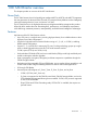
Non-port side of the DC SAN Director Figure 2 (page 10) shows a sample configuration of the non-port side view of the DC SAN Director. Figure 2 Non-port side of the DC SAN Director (sample configuration) 1. WWN bezel (logo plate) 2. Power supply 10 DC SAN Director overview 3.
DC SAN Director blades Table 1 (page 11) describes the Director, CP, and core switch blades that are available for the DC SAN Director. Table 1 Blades available for the DC SAN Director Description Name Function DC SAN Director CP blade CP8 The CP8 blade provides for management of all other blades in the DC SAN Director. There are two CP8 blades for redundancy. This CP blade is also compatible with the DC04 SAN Director.
High availability The following features contribute to the DC SAN Director high-availability design: • Redundant, hot-swappable blades and FRUs • Enhanced data integrity on all data paths • FSPF re-routing around failed links • Integration with SNMP managers • Automatic CP failover • Nondisruptive hot software code loads and activation • Easy configuration, save, and restore • Hot-swappable WWN cards The high-availability software architecture of the DC SAN Director provides a common framewo
• Predictive diagnostics analysis through Fabric Watch • SNMP (including version 3) integration with higher-layer managers Software features The Fabric OS allows any FC-compliant device to attach to the switches as long as it conforms to the device login, name service, and related FC standards. Each operating environment requires that an FC HBA be available with a standards-compliant driver for correct interface to the fabric.
Table 2 Security features (continued) Security Features Description Administrative domains/Virtual fabrics Firmware change alerts in Fabric Manager Boot PROM password reset Persistent port disable Password hardening policies Persistent domain ID Upfront login in WebTools E_Port disable Network manageability The DC SAN Director has a single domain and is managed as a single element with the optional FM GUI application.
Table 3 DC SAN Director orderable software licenses (continued) Option kit Part number HP Data Center Fabric Manager Professional+ TA754A HP B-Series Server Application Optimization LTU ALL TA759A HP Director FICON CUP LTU* Provides CUP management function designed to enable mainframe applications to perform configuration, monitoring, management, and statistics collection. T4401A *Supported in XP Storage array environments only.
Table 4 DC SAN Director orderable hardware (continued) Accessory Part number1 Optical transceivers HP 4Gb Short Wave B-series FC SFP 1 Pack AJ715A HP 4Gb Long Wave B-series FC SFP 1 Pack-10km AK870A HP 4Gb Extended Long Wave B-series FC SFP 1 Pack-30km AN211A HP 8Gb Short Wave B-series FC SFP+ 1 Pack AJ716A HP BLc 10Gb SR XFP Opt Kit 443756-B21 HP BLc 10Gb LR XFP Opt Kit 443757-B21 HP 8Gb Long Wave B-series FC SFP+ 1 Pack-10km AJ717A HP 8Gb Short Wave B-series FC MiniSFP 1 Pack BK789A HP 8
2 DC SAN Director installation This chapter provides information and instruction for installing a DC SAN Director. Time and items required for installation You can set up and install the DC SAN Director in the following ways: • As a standalone unit on a flat surface. • In a 19-in EIA cabinet, using the 14U Rack Mount Kit (ships with the DC SAN Director).
1. 2. 3. Provide a space that is 14 rack units (14U) high, 61.29 cm (24.09 in) deep, and 43.74 cm (17.22 in) wide. 1U is equal to 4.45 cm (1.75 in). Plan to install the DC SAN Director with the non-port side facing the aisle. The DC SAN Director can be installed facing either direction, if serviceability and cooling requirements are met. Plan for cable management before installing the chassis (see Managing cables (page 28)).
Items included with the DC SAN Director Table 6 (page 19) lists the items included with the standard shipment of the DC SAN Director.
Table 7 Items supplied with the 14U rack mount kit (DC SAN Director) (continued) Item Description Quantity B Right rack mount shelf bracket (rail brackets may differ from the illustration) 1 C 10-32 x 5/8 in (1.58 cm) panhead Phillips screw, washer (torque to 32 in-lb, 37 cm-kgs) 6 For cabinets that have rails with round holes D 10-32 clip nut 6 E 1/4-20 x 1/2 in (1.
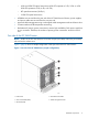
Attaching the shelf brackets Attach the left and right rack mount shelf brackets (Items A and B) to the cabinet rails adjustable ends installed on the side of the rack on the intake air aisle. 1. Locate the shelf brackets in the 14U Rack Mount Kit. 2. Locate and loosen the adjusting screws on the brackets (see Figure 4 (page 21), items A and B) to allow for adjustment to cabinet depth. Figure 4 Left and right shelf brackets installed on rails 3.
Figure 5 Shelf bracket and clip or retainer nut placement on cabinet rails NOTE: Standard EIA rails have holes in sets of three; spaces between the holes are 1.58 cm, 1.58 cm, and 1.27 cm (5/8 in, 5/8 in, and 1/2 in). If cables are to be routed down through the cable management comb, allow space below the brackets for cable management. 4. 5. Tighten the adjusting screws on the rack mount shelf brackets to a torque of 37 cm-kgs (32 in-lb).
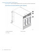
1. 2. 3. 4. Use a lift to raise the chassis to the correct level. Move the lift as close as possible to the rack, with the air-intake side of the chassis facing the front of the rack (see Figure 6 (page 24)). If applicable, lock the wheels of the lift. Gently slide the chassis onto the shelf brackets, ensuring that it remains supported during the transfer.
5. Fasten the port side of the chassis to the cabinet rails. Use three 10-32 x 5/8 in (1.58 cm) screws (Item C) per rail. Tighten the screws to a torque of 37 cm-kgs (32 in-lb). NOTE: Do not use the top or bottom holes of the DC SAN Director mounting bracket because the door will interfere with the screw heads. Figure 6 Positioning the DC SAN Director for installation in a cabinet 1. Rack cabinet (shown without sheet metal) 2.
Replacing the chassis door You must install the chassis door to ensure the DC Director meets EMI and other regulatory certifications. Additionally, if you do not use ICL cables, you must insert EMI plugs in the ICL cable ports to meet certification standards. NOTE: The door is not hinged. It installs on the chassis by snapping the four ball studs located on the chassis into the receiving hardware on the door. To replace the chassis door: 1.
Figure 8 Aligning the DC SAN Director door with the chassis Figure 9 Inserting DC SAN Director door on chassis ball studs 1. Ball stud on chassis (outside view of door) 3. Ball stud on chassis (inside view of door) 2. Mounting hardware Powering on the DC SAN Director CAUTION: Use the supplied power cords. Ensure the facility power receptacle is the correct type, supplies the required voltage, and is properly grounded. To power on the DC SAN Director: 1.
2. Connect the power cords to a power source with voltage of 200 to 240 VAC, 47 to 63 Hz (typically two power cords) or to a power source with voltage of 110 to 120 VAC, 47 to 63 Hz (two to four power cords). TIP: HP highly recommends use of the high-voltage line (200 to 240 VAC) due to better power-conversion efficiency. 3. Turn the AC power switches on the power supplies to ON. The AC power switches light green when switched on and power is supplied. 4.
the front panel diagram. The 1-GbE ports are 0 through 9 and are in both columns above the FC and 10GE ports. They are labeled GE on the front panel diagram. There are three FC trunking groups, defined as follows: • ◦ Trunk group 0: FC ports 0, 1 ◦ Trunk group 1: FC ports 6, 7 ◦ Trunk group 2: FC ports 2, 3, 4, 5, 8, 9, 10, 11 FCOE10-24 blade: Ports are numbered from 0 through 23 in two vertical rows, starting from the bottom left and ending at the top right.
NOTE: mSFP optical transceivers are compatible only with the FC8-64 port blade. While they will fit in other blades, this configuration is unsupported and generates an error. The ports are color-coded to indicate which can be used in the same port group for trunking (trunking port groups can be up to eight ports). The ports and cables used in trunking groups must meet specific requirements. See the Fabric OS Administrator’s Guide for more information. 1.
Figure 11 ICL connectors on CR8 blade 1. Status LED 4. ATTN LED 2. Power LED 5. ICL connector 3.
Figure 12 ICL connections (configuration 1) 1. Chassis 1 5. ICL connector (ICL 1) 2. Core switch blades (CR8) 6. ICL connector (ICL 0) 3. Core Processor blades (CP8) 7. ICL cables 4. Port blades 8.
Figure 13 ICL connections (configuration 2) 32 1. Chassis 1 5. ICL connector (ICL 1) 2. Core switch blades (CR8) 6. ICL connector (ICL 0) 3. Core Processor blades (CP8) 7. ICL cables 4. Port blades 8.
Figure 14 ICL connections (configuration 3) 1. Chassis 1 5. ICL connector (ICL 1) 2. Core switch blades (CR8) 6. ICL connector (ICL 0) 3. Core Processor blades (CP8) 7. ICL cables 4. Port blades 8.
Figure 15 ICL connections (configuration 4) 34 1. Chassis 1 5. ICL connector (ICL 1) 2. Core switch blades (CR8) 6. ICL connector (ICL 0) 3. Core Processor blades (CP8) 7. ICL cables 4. Port blades 8.
Figure 16 3-way ICL cable connections (configuration 1) 1. Chassis 1 4. Chassis 3 2. Core switch blades 5. ICL connector (ICL 1) 3. Chassis 2 6.
Figure 17 3-way ICL cable connections (configuration 2) 1. Chassis 1 4. Chassis 3 2. Core switch blades 5. ICL connector (ICL 1) 3. Chassis 2 6. ICL connector (ICL 0) The same general configuration applies regardless of which backbone chassis is used. To keep all three chassis in the same rack, you can use any combination of DC SAN Directors and DC04 SAN Directors, except three DC SAN Director chassis.
3 DC SAN Director login and configuration This chapter provides information and instructions for configuring the DC SAN Director. Configuration overview NOTE: If an FS8-18 encryption blade is installed, see the Fabric OS Encryption Administrator's Guide for information on configuring the encryption functions. You must configure the DC SAN Director before it is connected to the fabric. All configuration commands must be entered through the active CP blade.
tip /dev/ttyb -9600 When the terminal emulator application stops reporting information, press Enter. The following login prompt appears: CP0 Console Login: 6. Log in to the DC SAN Director as admin. The default password is password. At the initial login, the user is prompted to enter new admin and user passwords. Be sure to write down the new passwords and keep this information in a secure location. Fabric OS (swDir) swDir login: admin Password: Please change your passwords now.
4. Set up the CP1 IP address by entering the ipaddrset -cp 1 command: swDir:admin> ipAddrSet -cp 1 Enter the information at the prompts. This is a sample IP configuration: swDir:admin> ipaddrset -sw 0 Ethernet IP Address [0.0.0.0]: 123.123.123.120 Ethernet Subnetmask [0.0.0.0]: 123.123.123.123 Fibre Channel IP Address [0.0.0.0]: Fibre Channel Subnetmask [0.0.0.0]: Issuing gratuitous ARP...Done. Committing configuration...Done. swDir:admin> ipaddrset -cp 0 Host Name [cp0]: Ethernet IP Address [10.77.77.
NOTE: Changing the name causes a domain address format RSCN to be issued. To customize the switch name: 1. Enter switchName followed by the new name in double quotation marks. swDir:admin> switchName "swBrocadeDCX5" Committing configuration... Done. swBrocadeDCX5:admin> 2. Record the new name for reference. Customizing a chassis name For Fabric OS 6.2.
2. Position one of the optical transceivers so that the key is oriented correctly to the port. Insert the transceiver into the port until it is firmly seated and the latching mechanism clicks. Transceivers are keyed so that they can only be inserted with the correct orientation. If the transceiver does not slide in easily, ensure that it is correctly oriented. 3. Position a cable so that the key (the ridge on one side of the cable connector) is aligned with the slot in the transceiver.
NOTE: Passwords are not saved in the configuration file, and are not uploaded during a configUpload.
4 Monitoring DC SAN Director system components The DC SAN Director is engineered for reliability and requires no routine operational steps or maintenance. This chapter provides information about determining the status of each component using LEDs and CLI commands. Monitoring Director blade status To determine the status of a Director blade: 1. Observe the LEDs on the blade. • Figure 18 (page 44) shows the FC8-16. • Figure 19 (page 45) shows the FC8-32. • Figure 20 (page 46) shows the FC8-48.
Figure 18 FC8-16 Director blade 44 1. Power LED 3. FC port 2. Status LED 4.
Figure 19 FC8-32 Director blade 1. Power LED 3. FC port 2. Status LED 4.
Figure 20 FC8-48 Director blade 46 1. Power LED 3. FC port 2. Status LED 4.
Figure 21 FC8-64 Port blade 1.Status LED 3. Fibre Channel LED 2. Power LED 4.
Figure 22 FC10-6 Director blade 48 1. Power LED 3. FC port 2. Status LED 4.
Figure 23 FR4-18i Director blade 1. Power LED 3. FC port 2. Status LED 4.
Figure 24 FS8-18 encryption blade 50 1. Power LED 3. FC port 2. Status LED 4.
Figure 25 FX8-24 blade 1. 10-GbE ports 0–1 5. FC ports 0–5 2. 1 GbE ports 0–3 6. Power LED 3. 1 GbE ports 4–9 7. Status LED 4.
Figure 26 FCOE10-24 FCoE blade 1. 10-GbE FCoE ports 12–23 3. Power LED 2. 10-GbE FCoE ports 0–11 4. Status LED Table 8 Director blade LED descriptions LED purpose Power LED Status LED 52 Color Status Recommended action Steady green Blade has been enabled. No action required No light (LED is off) Blade has not been enabled. Ensure blade is firmly seated. No light (LED is off) Blade is either healthy or does not have power. Verify that the power LED is on.
Table 8 Director blade LED descriptions (continued) LED purpose FC Port Status Color Status Recommended action Steady amber Blade is faulty. Ensure blade is firmly seated and verify status with the slotShow command. If LED remains amber, contact HP. Slow-flashing amber (on 2 seconds, then off 2 seconds) Blade is not seated correctly or is faulty. Remove blade and reseat it. If LED continues to flash, replace blade.
Table 8 Director blade LED descriptions (continued) LED purpose 10-GbE Port Status (FCOE10-24) 1 Color Status Fast-flashing amber (on 1/4 second, then off 1/4 second) Transceiver or port is faulty. Change the transceiver or reset the switch from the workstation. No light (LED is off) Port is offline. Verify that the power LED is on, verify the transceiver and cable. Steady green Port is online but has no traffic.
Monitoring control processor blade (CP8) status To determine the status of a CP blade: 1. Observe the LED indicators on the CP blade (see Figure 27 (page 55)). The LED patterns may temporarily change during POST and other diagnostic tests. For information about how to interpret the LED patterns, see Table 9 (page 55). 2. Verify the port blade status by entering the slotShow and haShow commands. Figure 27 Control processor blade (CP8) 1. Status LED 5. Console port (10101) 2. Power LED 6.
Table 9 CP blade LED descriptions (continued) LED purpose Color Status Recommended action Status No light (LED is off) CP blade is either healthy or does Verify that the power LED is on. not have power. Steady amber CP blade is faulty or the switch is Ensure blade is firmly seated and still booting. switch has completed booting. If LED remains amber, contact HP. Slow-flashing amber (on 2 seconds, then off 2 seconds) CP blade is not seated correctly or is faulty. Remove the blade and reseat it.
Figure 28 Core switch blade (CR8) 1. Status LED 4. ATTN LED 2. Power LED 5. ICL connector 3. LINK LED Table 10 (page 58) describes the core switch blade LED patterns and the recommended actions for those patterns.
Table 10 CR blade LED descriptions LED purpose Color Status Recommended action Power Steady green CP blade has valid power. No action required No light (LED is off) CP blade does not have incoming power. Ensure blade is firmly seated and has power. No light (LED is off) CP blade is either healthy or does not have power. Verify that the power LED is on. Steady amber CP blade is faulty or the switch is still booting. Ensure blade is firmly seated and switch has completed booting.
Table 11 Power supply LED descriptions LED purpose Color Status Recommended action Power No light (LED is off) Power supply does not have incoming power and is not providing power to the DC SAN Director. Ensure power supply is firmly seated, DC SAN Director has incoming power, both power cables are connected, and AC power switches are on. Steady green Power supply has incoming No action required power and is providing power to the DC SAN Director. Flashing green Power supply is about to fail.
Table 12 Blower assembly LED descriptions LED purpose Color Status Recommended action Power No light (LED is off) Blower assembly does not have incoming power. Ensure that the blower assembly is firmly seated and has power. Steady green Blower assembly has incoming power. No action required No light (LED is off) Blower assembly is either healthy or does not have incoming power. Ensure that the blower assembly has incoming power. Steady amber Blower assembly has a failure (full or partial).
Figure 31 WWN bezel (logo plate) 1. CP blade Status (top) and Power (bottom) LEDs 3. Port blade Status (top) and Power (bottom) LEDs 2. CR blade Status (top) and Power (bottom) LEDs 4. Slot numbers Table 14 (page 61) describes the WWN card LED patterns and the recommended actions for those patterns. Table 14 WWN bezel LED descriptions LED purpose Color Status Recommended action nl Port blade/CP blade/ CR blade Power Steady green Power is OK.
5 Replacing DC SAN Director FRUs This chapter provides information for replacing the field-replaceable components. IMPORTANT: The FRUs in the DC SAN Director can be removed and replaced without special tools. The DC SAN Director can continue operating during many of the FRU replacements if the conditions specified in the procedure are followed. Replacing the chassis door The chassis door must be installed to ensure the DC SAN Director meets EMI and other regulatory certifications.
Replacing the cable management comb The replacement procedure for the cable management comb takes less than five minutes and requires a #1 Phillips screwdriver. Removing a cable management comb CAUTION: Wear a grounded ESD strap when handling DC SAN Director components. The Director chassis provides a grounding connection above the power connectors. Also, store ESD-sensitive components in antistatic packaging. To remove the cable management comb: 1. Remove the chassis door.
Replacing a Director blade This section describes how to remove and replace a Director blade. The replacement procedure for each Director blade takes less than ten minutes.
11. FC8-16, FC8-32, FC8-48, FC8-64, FS8-18, FX8-24, FCOE10-24 blades: Open the ejectors. Remove the blade from the chassis using the ejectors. FC10-6 and FR4-18i blades: Use the Phillips screwdriver to unscrew the two thumb screws from the top and bottom ejectors on the blade. Open both ejectors simultaneously to approximately 45 degrees and remove the blade from the chassis. 12. If the blade is not being replaced by another blade, install a filler panel.
3. FC10-6 and FR4-18i blades: Close the ejectors by pushing the handles toward the center of the blade until the ejectors lock. The levering action of the handles seats the blade in the slot. FC8-16, FC8-32, FC8-48, FC8-64, FS8-18, FX8-24, FCOE10-24 blades: Adjust the ejectors to the closed position by pulling them away from the center of the blade. 4. FC10-6 and FR4-18i blades: a. Use the Phillips screwdriver to tighten the thumb screw inside each handle. See Figure 34 (page 65). b.
4. Replace the chassis door (see Installing the chassis door (page 62)). Figure 35 Director blade filler panel Replacing a control processor blade (CP8) This section describes how to remove and replace a control processor (CP8) blade. Each DC SAN Director has two CP8 blades, which are located in slot 6 and slot 7. NOTE: If the new CP blade does not have the same firmware as the active CP blade, you must upgrade the new blade to the active CP blade firmware version.
Determining whether or not to replace a CP blade The following events can indicate that a CP blade is faulty: • The status LED on the CP blade is amber, or the power LED is not lit. • The CP blade does not respond to Telnet commands, or the serial console is not available. • The slotShow command does not show that the CP blade is enabled. • The haShow command indicates an error. • The clock is inaccurate, or the CP blade does not boot up or shut down properly.
b. Enter the haFailover command. The functioning CP blade becomes the active CP blade. c. d. Wait until the status LED on the functioning CP blade is no longer lit. Enter the haShow command from the functioning CP blade (the new active CP blade) to verify the failover.
Removing a control processor blade (CP8) The DC SAN Director continues to operate while a CP blade is being replaced if the redundant CP blade is active and a failover does not occur. You can prevent failover by entering the haDisable command. CAUTION: Wear a grounded ESD strap when handling DC SAN Director components. The Director chassis provides a grounding connection above the power connectors. Also, store ESD-sensitive components in antistatic packaging. IMPORTANT: Director.
Installing a control processor blade (CP8) CAUTION: Wear a grounded ESD strap when handling a CP8 blade. Use the grounding connections above the power connectors on the chassis. To install a CP blade (slot 6 or 7): 1. Open the ejector handles to approximately 45 degrees. Orient the CP blade so that the handles are toward you and the flat metal side is on your left. 2. Align the flat metal side of the CP blade inside the lower and upper blade guides in the slot.
Primary partition: v6.0.0 Secondary Partition: v6.0.0 Remote CP (Slot 6, CP0): Standby Primary partition: v6.0.0 Secondary Partition: v6.0.0 Note: If Local CP and Remote CP have different versions of firmware, please retry firmwaredownload command. swDir:admin> 6. 7. If the firmware version on the replacement blade does not match that on the active CP blade, bring the replacement blade to the same firmware level as the active blade.
Replacing a core switch blade (CR8) This section describes how to remove and replace a core switch blade. Each DC SAN Director integrates two core switch blades, which are located in slot 5 and slot 8. The replacement procedure for the core switch blade takes approximately 30 minutes.
To remove a CR blade: 1. Remove the chassis door. See Removing the chassis door (page 62). 2. Power off the blade by sliding the slider switch in the top ejector down to the off position (see Figure 37 (page 74)). 3. Disconnect cables from the faulty core switch blade. 4. Use the Phillips screwdriver to unscrew the thumb screw from both ejectors. 5. Open both ejector handles simultaneously to approximately 45 degrees and remove the core switch blade from the chassis (see Figure 37 (page 74)).
8. Replace the chassis door. See Installing the chassis door (page 62). Replacing a power supply The DC SAN Director can continue operating during the replacement if at least one power supply continues operating. The replacement procedure for each power supply takes less than five minutes. A power supply unit or filler panel is required for the power supply replacement. Removing a power supply CAUTION: Wear a grounded ESD strap when handling DC SAN Director components.
4. Verify that the power LED on the power supply displays a steady green light. Figure 38 Power supply Replacing a blower assembly IMPORTANT: To ensure continuous adequate cooling, maintain three operating blower assemblies at all times except for the brief period when replacing a blower assembly. The procedure for each blower assembly takes less than five minutes.
1. 2. 3. Orient the blower assembly and slide it into the chassis, pushing firmly to ensure that it is seated. Verify that the power LED displays a green light. Use the screwdriver or your fingers to tighten the captive screws. Figure 39 Blower assembly Replacing the WWN bezel (logo plate) and WWN card The WWN cards contain fully redundant circuits and typically do not require replacement. Two WWN cards are located beneath the WWN bezel (logo plate). Allow approximately 20 minutes to replace a WWN card.
1. Observe the LED indicators on the WWN bezel and verify that they reflect the actual status of the components. The WWN bezel covers the WWN cards and allows its LEDs to shine through. The LEDs on the WWN bezel provide a consolidated view of the port, CP, and CR blade status (see Table 15 (page 78)). If a blade slot has a filler panel installed, the corresponding LEDs on the WWN card do not illuminate.
Removing the WWN bezel (logo plate) and WWN card CAUTION: Wear a grounded ESD strap when handling the WWN card. Use the grounding connections above the power connectors on the chassis. To remove the WWN bezel and WWN card: 1. Open a Telnet session to the DC SAN Director and log in to the active CP as admin. The default password is password. 2. Verify that you are logged into the active CP. Enter the haShow command to determine the active CP. 3.
Figure 40 WWN bezel (logo plate) and WWN card Installing the WWN bezel (logo plate) and WWN card CAUTION: Wear a grounded ESD strap when handling the WWN card. Use the grounding connections above the power connectors on the chassis. To install the WWN bezel and WWN card: 1. Unpack the new WWN card and save the packaging for the faulty WWN card. 2. Install the WWN card as follows: 3. 4. • To install a WWN card that has handles: Hold the card by the handles and orient with the LEDs at the bottom.
NOTE: 7. The LEDs can take up to two minutes after WWN card installation to begin functioning. Pack the faulty WWN card in the packaging provided with the new card and return it to the DC SAN Director supplier. Replacing SFPs, SFP+s, mSFPs, and XFPs NOTE: The 8-Gb/s mSFPs and SFP+s autonegotiate at 2, 4, and 8 Gb/s. The 4-Gb/s SFPs autonegotiate at 1, 2, and 4 Gb/s. The XFP transceivers are used only with the FC10-6 port card. They should not be used in any 1 GE port.
Figure 42 mSFP optical transceiver 1. Pull tab 2. mSFP optical transceiver Replacing an mSFP optical transceiver 1. 2. Insert the cable into the new transceiver until the latching mechanism clicks. Position the optical transceiver so that the key is oriented correctly to the port. Insert the transceiver into the port until it is firmly seated and the latching mechanism clicks. Transceivers are keyed so that they can be inserted only with the correct orientation.
• A surface to place the old chassis on, such as a second lift or the pallet originally provided with the old chassis • #2 Phillips screwdriver Verifying the need to replace the chassis To verify that it is necessary to replace the chassis, ensure that the components are firmly seated, troubleshoot the chassis following the list below, and contact your support provider with any remaining questions about whether the chassis should be replaced.
Table 18 Critical information checklist (continued) Notes regarding supportshow output: Information about the new chassis New Factory Serial Number: New Serial Number (if available): To record critical DC SAN Director and SAN information: 1. Open a Telnet session and log in to the DC SAN Director as admin. The default password is password. Enable the logging function on your Telnet or serial console connection. 2. Back up the current configuration.
3. Record the DC SAN Director values on a workstation: a. Record the WWN value. Enter the wwn command, and then copy the command output into a file named config-miscinfo.txt. rsl8-st03-dcx-1:admin> wwn 10:00:00:60:69:00:00:0a b. Record the IP address information. Enter the ipAddrShow -sw command, and then copy the command output into the config-miscinfo.txt file. rsl8-st03-dcx-1:admin> ipAddrShow -sw SWITCH Ethernet IP Address: 10.32.50.12 Ethernet Subnetmask: 255.55.0.0 Fibre Channel IP Address: 1.2.3.
Factory Part Num: Factory Serial Num: Manufacture: Update: Time Alive: Time Awake: 60-0001501-07 FT02X805BE2 Day: 26 Month: Day: 14 Month: 207 days 3 days 3 3 Year: 2007 Year: 2009
Disconnecting from the network and the fabric To disconnect from the network and fabric: 1. Shut down the DC SAN Director using the sysShutdown command. rsl8-st03-dcx-1:admin> sysshutdown This command will shutdown the operating systems on your switch. You are required to power-cycle the switch in order to restore operation. Are you sure you want to shutdown the switch [y/n]?y HA is disabled Stopping blade 1 Shutting down the blade.... Stopping blade 4 Shutting down the blade....
3. Unpack the new chassis: a. Cut the bands that encircle the packaging. b. Remove the lid, kits, and foam from the top of the chassis. c. Lift the cardboard box off the chassis and remove the plastic bag from around the chassis. Save the packing materials for use when returning the old chassis. d. Leave the chassis on top of the plastic shipping tray if the chassis must be transported to the installation location. 4.
NOTE: If you are using the VF feature, run the configDownload -vf command before running the configUpload command in order to restore the logical switch configuration. 2. Enter the configDownload command. Server Name or IP Address [host]: 123.123.123.123 nl User Name [None]: Admin24 nl File Name [config.txt]: config-switch.txt nl Password: xxxxxxxx nl download complete nl switch:admin> 3. Reboot the DC SAN Director.
d. Verify that the command displays the correct serial numbers. rsl8-st03-dcx-1:root> fruinfoset chassis 1 ID: (none) > PN: (none) > SN: (none) > OEMssn12345 RV: (none) > Chassis SN: (none) > FT00X8008A4 New FRU Info for: chassis(wwn) 1 ID: none PN: none SN: OEMssn12345 RV: none Chassis SN: FT00X8008A4 rsl8-st03-dcx-1:root> 3. Verify that the chassis serial number has been entered correctly by entering the chassisShow command at the prompt.
switchWwn: zoning: switchBeacon: blade3 Beacon: blade5 Beacon: blade8 Beacon: blade10Beacon: 10:00:00:05:1e:39:59:67 OFF OFF OFF OFF OFF OFF Index Slot PortAddressMediaSpeedStateProto =========================================================== 32 3 00b2000idN4OnlineL-Port 5 public 33 3 10b2100__N8No_Module 34 3 20b2200__N8No_Module 35 3 30b2300__N8No_Module 36 3 40b2400idN4OnlineF-Port 10:00:00:00:c9:51:00:2d 37 3 50b2500__N8No_Module rsl8-st03-dcx-1:admin> 4.
2. Reconnect the transceivers and cables to the port blades. NOTE: The ports and cables used in trunking groups must meet specific requirements. For a list of these requirements, see the Fabric OS Administrator's Guide. a. b. c. Position one of the transceivers so that the key is oriented correctly to the port and insert the transceiver into the port until it is firmly seated and the latching mechanism clicks.
Verifying that the configuration of the fabric is correct HP recommends that you copy the command outputs from this section into a file. To verify correct configuration of the fabric: 1. Create an “after” SAN profile by entering the following commands and copying the output to a text file named SANafter.
3. Resolve any issues or unintentional changes to the DC SAN Director or fabric. • If there are any mechanical problems, try reseating the associated component. • If the configuration information is not correct for the DC SAN Director, modify as required. If necessary, the configuration saved before the replacement can be downloaded using the configDownload command.
Table 19 Cable routing table for DC SAN Director (48 ports shown) (continued) Slot/port Slot Cable labels Port Switch end Connected device Slot/port of device Device end 18 19 20 21 22 23 24 25 26 27 28 29 30 31 32 33 34 35 36 37 38 39 40 41 42 43 44 45 46 47 48 Replacing the DC SAN Director chassis 95
6 Support and other resources HP technical support For worldwide technical support information, see the HP support website: http://www.hp.
• http://www.hp.com/support/manuals • http://www.hp.com/support/downloads Rack stability Rack stability protects personnel and equipment. WARNING! To reduce the risk of personal injury or damage to equipment: • Extend leveling jacks to the floor. • Ensure that the full weight of the rack rests on the leveling jacks. • Install stabilizing feet on the rack. • In multiple-rack installations, fasten racks together securely. • Extend only one rack component at a time.
Typographic conventions Table 20 Document conventions Convention Element Blue text: Table 20 (page 98) Cross-reference links and email addresses Blue, underlined text: http://www.hp.
A Technical specifications This appendix provides information for the DC SAN Director. General specifications The DC SAN Director is compliant with United States and International safety and EMC Electromagnetic Compatibility standards. Table 21 (page 99) lists the general specifications for the DC SAN Director .
System architecture Table 22 DC SAN Director system architecture FC Ports Up to 256 ports, universal (E_Port, F_Port, FL_Port, Ex_Port, and M_Port) Control processor Redundant (active/standby) control processor modules Scalability Full fabric architecture: 239 switches maximum Performance 1.063 Gb/s line speed, full duplex 2.125 Gb/s line speed, full duplex 4.25 Gb/s line speed, full duplex 8.50 Gb/s line speed, full duplex 10.
Table 22 DC SAN Director system architecture (continued) NOTE: Self-discovery is based on switch type (U_Port) with an optional port type control. See the Fabric OS Administrator's Guide for details on any limitations of port type based on configuration. Data traffic types Fabric switches supporting unicast, multicast (255 groups), and broadcast Media types Hot-pluggable, industry-standard SFP or XFP (FC10-6 only) LC connector: • SWL, up to 500 m (1,640 ft) • LWL, up to 10 km (6.
Table 24 System FRU weights (continued) FRU Weight FC8-16 port blade 3.0 kg (6.6 lb) without media FC8-32 port blade 3.27 kg (7.2 lb) without media FC8-48 port blade 3.36 kg (7.4 lb) without media FC8-64 port blade 3.36 kg (7.4 lb) without media FC10-6 port blade 3.1 kg (6.8 lb) without media FR4-18i application blade 3.36 kg (7.4 lb) without media FS8-18 encryption blade 5.5 kg (12.0 lb) FX8-24 Extension blade 4.2 kg (9.2 lb) without media FCOE10-24 FCoE blade 3.72 kg (8.
DC SAN Director The power subsystem is a redundant +48 VDC power distribution system with a provision for up to four 1,000 W, 48 VDC bulk power supplies. Four bulk power supplies produce the intermediate distribution voltage in the distributed power system. The power specifications in Table 25 (page 103) are calculated for fully loaded systems with four power supplies. A fully loaded system has eight FC8-48 port blades, two CP8 blades, two CR8 blades, and three blower assemblies.
Table 26 Power cord types (international) (continued) Plug style NEMA 5–20P 125V only USA, Canada, Mexico, other locations NEMA L6-20 USA, Canada, Mexico, other locations CEE-7/7 “Schuko” Continental Europe BS-1363A AS 3112 IEC-60309 Australia/New 32A-6h, Zealand 230V C20 20A-250V 12 AWG connect to in-cabinet power strip only.
Table 26 Power cord types (international) (continued) Plug style NEMA 5–20P 125V only USA, Canada, Mexico, other locations NEMA L6-20 USA, Canada, Mexico, other locations X X CEE-7/7 “Schuko” Continental Europe BS-1363A AS 3112 IEC-60309 Australia/New 32A-6h, Zealand 230V C20 20A-250V 12 AWG connect to in-cabinet power strip only.
Power cords (Japan, Denan) Environmental requirements Table 27 (page 106) lists the environmental operating ranges for the DC SAN Director. The requirements for non-operating conditions are also provided for acceptable storage and transportation environments.
Data transmission ranges Table 28 (page 107) and Table 29 (page 107) provide the data transmission ranges for different cable types and port speeds. Table 28 Supported single mode cable speeds and distances Cable type 9 microns 1 Speed Minimum distance Maximum distance (LWL) Maximum distance (ELWL) 2 Gb/s 2m 10,000 m 25,000 m1 4 Gb/s 2m 10,000 m 25,000 m1 8 Gb/s 2m 10, 000 m 25,000 m1 The maximum distance for the AN211A is 30,000 m.
B Intelligent blades This appendix provides information for the following blades: • B-series MP Router blade (FR4-18i) • HP DC Switch Encryption FC blade (FS8-18) • DC Director Switch MP Extension blade (FX8-24) • DC SAN Director 10/24 FCoE blade (FCOE10-24) B-series MP Router blade (FR4-18i) overview NOTE: The B-series MP Router blade (FR4-18i) is used in the DC SAN Director .
2. 3. 4. Ensure the latches on the FR4-18i blade are unscrewed and open. Slide the FR4-18i blade into the open slot. Close the latches, tighten the screws, and power on the blade using the ON/OFF slider switch (see Figure 43 (page 109)). The FR4-18i blade begins POST. After POST is complete, the firmware version on the blade will autolevel with the firmware version on the active CP. 5. Verify that the blade power and blade status LEDs are green after the blade has completed booting.
Configuring FCIP and FC Routing Services and enabling the ports The ports on the FR4-18i blade are initially set to persistently disabled. If you want to enable the FC ports as a standard E_Port or F_Port, use the portcfgpersistentenable command to enable the ports. If you are using the FC ports as EX_Ports, you must configure the FC Routing Services feature prior to enabling the ports. The GbE ports can only be used after you have configured FCIP and enabled the VE_Ports.
Recommendations for cable management Manage cables as follows: • Plan cable management before installing the blade. • Leave at least one meter of slack for each port cable. This provides room to remove and replace the blades, and helps prevent the cables from being bent to less than the minimum bend radius. HP DC Switch Encryption FC blade (FS8-18) overview NOTE: The HP DC Switch Encryption FC blade (FS8-18) is used in the DC SAN Director .
Configuring the FS8-18 blade For information on configuring the encryption functions, see the Fabric OS Encryption Administrator's Guide. Cabling the FS8-18 blade To cable the FS8-18 blade: 1. Install the SFP transceivers in the FC and GbE ports, as required: a. Remove the rubber plugs from the ports to be used. b. Position the transceiver so that it is oriented correctly and insert it into a port until it is firmly seated and the latching mechanism clicks.
DC Director Switch MP Extension blade (FX8-24) overview The FX8-24 blade has 12 external 8Gb FC SFP ports supporting FC Routing Services, and 10 external 1-Gb Ethernet (GbE or GE) SFP ports supporting FCIP. There are also two licensable external 10-Gb Ethernet (10GbE or 10GE) SFP ports supporting FCIP. The FX8-24 blade operates with Fabric OS 6.3.
• Support for 200-ms RTT (on a limited number of GbE ports) • Adaptive Rate Limiting (licensable) • FICON Accelerator (licensable) • TCP performance graphing in WebTools • FCIP Tunnels • ◦ A maximum of 10 FCIP tunnels is allowed for all GbE ports. ◦ A maximum of four tunnels is allowed per GbE port. ◦ Two 10 GbE ports that support up to ten FCIP tunnels each. ◦ Individual FCIP tunnels are represented and managed as a virtual FC E_Port. ◦ FC Routing Services are used over the FCIP link.
• Standard Ethernet encapsulation • End-of-row deployment DC SAN Director 10/24 FCoE blade (FCOE10-24) overview 115
C Regulatory compliance and safety notices This appendix provides the following information: • Regulatory compliance notices (page 116) • International notices and statements (page 117) • Environmental regulation compliance (page 119) • Safety guidelines (page 121) Regulatory compliance notices Federal Communications Commission notice for Class A equipment This equipment has been tested and found to comply with the limits for a Class A digital device, pursuant to Part 15 of the FCC Rules.
Certification and classification information This product contains a laser internal to the fiber optic (FO) transceiver for connection to the FC communications port. In the U.S., the FO transceiver is certified as a Class 1 laser product conforming to the requirements contained in the Department of Health and Human Services (DHHS) regulation 21 CFR, Subchapter J. A label on the plastic FO transceiver housing indicates the certification.
Japanese notice Figure 46 Japanese notice Korean notices Figure 47 (page 118) and Figure 48 (page 118) show the Korean notices.
Environmental regulation compliance This section describes the China RoHS environmental regulatory compliance requirements for the HP DC SAN Backbone Director Swich . China RoHS The following are the requirements of the People's Republic of China- Management Methods for Controlling Pollution by Electronic Information products.
Table 30 Hazardous substances (continued) Name of the Component Hazardous/Toxic Substance/Elements Lead (PB) Mercury (Hg) Cadmium (Cd) Hexavalent Chromium (CR6+) Polybrominated Biphenyl (PBB) Polybrominated Diphenyl Ether (PBDE) Sheet metal X O O O O O Chassis assembly X O O O O O Mechanical brackets and slides X O O O O O Slot filler X O O O O O Cable management comb X O O O O O Cable comb O O O O O O Cables and power cords O O O O O O Replacement door
Safety guidelines The following sections summarize ways to maintain a safe operating environment for the Director. Electrostatic discharge recommendations CAUTION: To prevent damaging the system, be aware of the precautions you need to follow when setting up the system or handling parts. A discharge of static electricity from a finger or other conductor may damage system boards or other static-sensitive devices. This type of damage can reduce the life expectancy of the device.
To prevent electrostatic damage, observe the following precautions: • Avoid hand contact by transporting and storing products in static-safe containers. • Keep electrostatic-sensitive parts in their containers until they arrive at static-free workstations. • Place parts on a grounded surface before removing them from their containers. • Avoid touching pins, leads, or circuitry. • Always make sure you are properly grounded when touching a static-sensitive component or assembly.
using the HP spare part designated for this product. For more information about battery replacement or proper disposal, contact an HP authorized reseller or HP authorized service provider. WARNING! Your switch contains an internal lithium manganese dioxide, a vanadium pentoxide, or an alkaline battery pack. There is risk of fire and burns if the battery pack is not properly handled. To reduce the risk of personal injury: • Do not attempt to recharge the battery.
Chinese warning messages Altitude warning message May be used safely only in areas where the attitude is less than 2000m. Non-tropical warning message May be used safely only in non-tropical climates.
D Port numbering templates Print or copy the templates on the following pages and use them to document the port numbering pattern for the DC SAN Director .
Figure 49 Port side populated with eight FC8-48 port blades, two CR8 blades, and two CP8 blades 126 Port numbering templates
Figure 50 Port side populated with eight FC8-32 port blades, two CR8 blades, and two CP8 blades DC SAN Director templates 127
Figure 51 Port side populated with eight FC8-16 port blades, two CR8 blades, and two CP8 blades 128 Port numbering templates
Figure 52 FC10-6 port blades DC SAN Director templates 129
Figure 53 FR4-18i router blades 130 Port numbering templates
Figure 54 FS8-18 encryption blades DC SAN Director templates 131
Figure 55 FX8-24 Extension blade 132 Port numbering templates
Figure 56 FCOE10-24 FCoE blade DC SAN Director templates 133
Glossary This glossary defines acronyms and terms used in this guide and is not a comprehensive glossary of computer terms. A ACL Access control list. A data protection feature used to restrict access to data resources based on defined policies. AES Advanced Encryption Standard. An encryption security technology. API Application Programming Interface. ASIC Application-Specific Integrated Circuit. B B-series FC switches and FICON directors manufactured for HP by Brocade Communications Systems, Inc.
F fabric A network of one or more FC switches that transmit data between any two N_Ports on any of the switches. failover An automatic method for transferring operations from a failed system to a secondary, identical system. FC Fibre Channel. A comprehensive set of standards for concurrent communication among servers, storage systems, and peripheral devices. FC-SP Fibre Channel Security Protocol. A security protocol that protects in-transit data. FCC Federal Communications Commission.
LTU License to use. LUN Logical unit number. An identification scheme for storage disks. LWL Long-wave laser. M MIB Management Information Base (B-series). MP Router Multi-protocol Router. MPIO Multipath I/O (Microsoft software). MUAs Multiple user accounts. N NTP Network time protocol. NVRAM Nonvolatile RAM P PID Port identifier. platform A combination of supported hardware components and operating system on a server from a specific vendor. POST Power-on self-test.
SP Service pack. A collection of software updates. SPOCK Single Point of Connectivity Knowledge. An HP website as the primary portal to obtain detailed information about supported HP product configurations (http://www.hp.com/storage/spock). An HP Passport account is required for access. SR Short Reach SSH Secure Shell. A security encryption protocol. SWL Short-wave laser. T topology The physical structure of interconnected components that form a network. U V VF Virtual fabric.
Index A accumulators, 123 Avis Canadien, regulatory compliance notice, 117 B back up configuration, DC, 41 batteries recycling or disposal, 123 replacement notice, 122 Taiwan EPA recycling and disposal, 123 bezel, WWN, DC replacing, 77 blade FCOE10-24, 114 FR4-18i, 108 FS8-18, 111 FX8-24, 113 blade, DC CP, LEDs, 55 CP, status, 55 CR, LEDs, 57 CR, status, 56 Director, replacing, 64 port, status, 43 blades weight, 101 blades, DC available for, 11 support for, 7 blower assembly, DC replacing, 76 status, 59 C
environmental, requirements, 106 Ethernet, establish connection, DC, 39 European Union, regulatory compliance notice, 117 extension blade, 113 F fabric, connecting DC to, 40 facility requirements, 102 FC port specifications, 106 Routing Services, 108 FCC (Federal Communications Commission) modifications, 116 FCoE blade, 114 FCOE10-24 blade, 114 features, DC, 7 field-replaceable units, DC See FRUs, DC, 8 filler panel, DC replacing, 66 FR4-18i blade, 108 FRUs blades, weights, 101 FRUs, DC blower assembly, 59
R U rack stability warning, 97 recycling, battery, 123 recycling, Taiwan EPA battery, 123 regulatory compliance information number, 116 notices Canada, 117 European Union, 117 HP series number, 116 IEC EMC statement, worldwide, 117 Japan, 118 Korean, 118 lasers, 116 modifications, 116 shielded cables, 116 related documentation, 96 reliability features, DC, 12 removal and replacement procedures, DC, 62 replacing a power cord, 123 requirements, facility, 102 RFI/EMI connector hoods, 116 router blade, 108 u