
HP DC SAN Backbone Director Switch Hardware Reference Guide (5697-2158, August 2012)


NOTE: mSFP optical transceivers are compatible only with the FC8-64 port blade. While they
will fit in other blades, this configuration is unsupported and generates an error. The ports are
color-coded to indicate which can be used in the same port group for trunking (trunking port groups
can be up to eight ports). The ports and cables used in trunking groups must meet specific
requirements. See the Fabric OS Administrator’s Guide for more information.
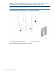
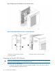
1. Position one of the optical transceivers so that the key is oriented correctly to the port. Insert
the transceiver into the port until it is firmly seated and the latching mechanism clicks.
Transceivers are keyed so that they can only be inserted with the correct orientation. If the
transceiver does not slide in easily, ensure that it is correctly oriented.
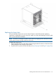
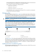
2. Position a cable so that the key (the ridge on one side of the cable connector) is aligned with
the slot in the transceiver. Insert the cable into the transceiver until the latching mechanism
clicks.
Cables are keyed so that they can be inserted in only one way. If a cable does not slide in
easily, ensure that it is correctly oriented.
3. Repeat step 1 and step 2 for the remaining ports.
4. Organize the cables (see Managing cables (page 28)).
5. Verify the DC Director and port status using the switchShow command.
6. Verify fabric connectivity using the fabricShow command.
Using the optional HP DC SAN Director Inter-Chassis Link cable kit
To connect two DC SAN Directors together without using any FC ports on the port blades, purchase
the optional HP DC SAN Director Inter-Chassis Link cable kit, HP part number AK862A. The kit
increases the number of ports by interconnecting two DC SAN Director chassis.
NOTE: For Fabric OS 6.4.0 and later, three DC SAN Director chassis can be supported in a
triangular ICL configuration, as long as the third chassis is housed in an immediately adjacent
rack, so that the cables reach the ICL ports.
To connect a DC SAN Director to a DC04 SAN Director, purchase the following:
• Two HP DC04 SAN Director ICL LTU (TA642A)
• One HP DC SAN Director Inter-Chassis Link Cable Kit (AR480A)
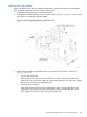
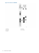
The ICL cables and the ICL connectors (see Figure 11 (page 30)) are color-coded and labeled for
ease of installation.
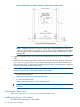
Figure 12 (page 31) through Figure 17 (page 36) show the acceptable cabling configurations for
the option. Connect the ICL cables in one of the configurations shown.
IMPORTANT: If ICL cables are not in use, the ports must have EMI plugs installed to meet EMI
and other regulatory certifications.
NOTE: Connect the cables from the top connectors (ICL 1) of the CR8 blades in the first chassis
to the bottom connectors (ICL 0) of the CR8 blades in the second chassis. Similarly, connect the
cables from the bottom connectors (ICL 0) of the CR8 blades in the first chassis to the top connectors
(ICL 1) of the CR8 blades in the second chassis.
Pay special attention to this configuration when creating a 3-way connection between three chassis.
The ports and cable connectors are color-coded to help ensure correct orientation.
The cables can cross between the slot 5 CR8 blade and the slot 8 CR8 blade provided the
top-to-bottom rule is followed.
Using the optional HP DC SAN Director Inter-Chassis Link cable kit 29