
HP B-series 16Gb FC Switches Quick Start Instructiions

NOTE: For switches with Port Side Air Intake,
install the Rack Mount Kit so that when the
switch is installed the port side faces the front
of the rack.
To install the switch in a rack using the Rack Mount
Kit:
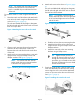
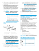
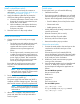
1. Place the switch on a flat surface and attach each
inner rail to the switch using three flat-head screws
as shown in Figure 4 (page 4).
The rails are labeled Left and Right to designate
the left side and right side of the switch as viewed
from its non-port side.
Figure 4 Attaching the inner rails to the switch
2. Choose a rack mounting location that provides
clearance for the switch power cords to run
between the rack sides and the rails at the front
of the rack.
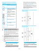
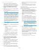
3. Attach each rear mounting bracket to a rear rack
upright column using two Phillips screws and
adapter washers. See Figure 5 (page 4).
NOTE: For switches with Port Side Air
Intake, attach the rear mounting brackets
to the front rack upright column.
Figure 5 Installing the rear mounting brackets
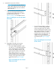
4. Attach each outer rail as shown in Figure 6 (page
4).
The rails are labeled Left and Right to designate
the left side and right side of the rack as viewed
from the front of the cabinet.
NOTE: For switches with Port Side Air
Intake, attach Left outer rail to the right side
of the rack and Right outer rail to the left
side of the rack.
Figure 6 Attaching the outer rails
a. Slide the rail over the rear mounting bracket.
b. Attach the front of the rail to a front rack
upright column using two Phillips screws and
adapter washers.
c. Attach the outer rail to the rear mounting
brackets using a Phillips screw.
TIP: Tighten the rear screws just
enough for the end of the screw to go
through the rear bracket. Later in the
procedure, you will need room to slide
the inner rail between the screw head
and the outer bracket.
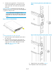
5. From the front of the rack, slide the switch (with
inner rails attached) onto the outer rails, taking
care to align the inner rails with the attachment
screws on the outer rails at the rear of the rack.
See Figure 7 (page 4).
Figure 7 Installing the switch in the rack
Page 4