HP Surestore NAS 8000 SAN Solution Integration Manual (SIM) 1 Read Me First This binder includes the details of the integration tasks that Hewlett-Packard or an authorized reseller has performed. The first section, Solution Integration and Product Configuration Overview, is intended to give you the best knowledge about the solution you ordered from Hewlett Packard.
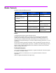
Binder Contents This binder contains the following sections: Section Audience Purpose 1. Read Me First Customer IT administrator Introduction 2. Solution Integration and Product Configuration Overview Customer IT administrator Product information 3. Network and Storage Planning Installation specialist and customer IT administrator Pre-installation planning session 4. Installation Guide Installation specialist Hardware installation and software configuration 5.
Solution Integration and Product Configuration Overview 2 This section contains the following documents, which were customized and inserted by the Integration Center: ■ Deployment information ■ Rack, server and component configurations ■ Parts list ■ Network, cabling, and power connection diagrams Solution Integration and Product Configuration Overview 3
Solution Integration and Product Configuration Overview
3 Network and Storage Planning This section contains pre-planning materials that the installation specialist can review with the customer before the NAS 8000 system arrives onsite. It includes: ■ System Overview: a conceptual overview of the storage system of the HP NAS 8000 SAN, including: — Storage Overview and Terminology — Basic Storage Configuration — Determining Available Disk Space ■ Planning Worksheets: to record network and storage settings for the HP NAS 8000 SAN system.
Storage Overview and Terminology The HP NAS 8000 SAN is an easy-to-manage storage solution for heterogeneous environments including Windows, UNIX, and Linux. The storage space on the HP NAS 8000 SAN is made up of physical and logical storage: ■ Physical storage refers to the hardware used for data storage. ■ Logical storage is created by software that organizes physical storage into file volumes and directories that are made accessible to users.
Snapshots Snapshots are an important part of data-protection plans. A good data-protection plan should include a backup strategy, storage redundancy provided by RAID levels, and snapshots. Snapshots provide nearly instantaneous access to previous versions of a file stored on the HP NAS 8000 HA solution. A snapshot is a read-only picture of a file volume at a specific point in time. When you create a snapshot of a file volume, the snapshot initially consumes zero physical space.
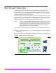
Basic Storage Configuration The most basic storage configuration consists of one LUN and one Volume Group. This configuration provides access to the full amount of available disk space and allows you to subdivide the entire capacity into multiple file volumes and snapshots. While this is the most flexible setup for a system with all physical storage on a single array, using a single volume group limits options for future system upgrades.
The HP NAS 8000 SAN system also supports multiple LUNs and volume groups. This configuration is more flexible for future upgrades and allows upgrades to an HA cluster without having to lose the storage configuration or any data. For maximum flexibility in the use of storage space, do not create large numbers of volume groups. You can divide volume groups into separate file volumes to segregate storage for separate users, departments or purposes.
Planning Worksheets The following topics should be reviewed in a planning session with the customer prior to installation: ■ Available disk space ■ LUN, volume group and file volume requirements ■ Network settings The planning worksheets in this section provide space to collect the information needed to install the system. The blank worksheets are also included on the HP NAS 8000 Documentation CD.
Storage Planning Worksheet Note All space is in Gigabytes (GB). 1. Record total available storage space Instructions Total available storage Ask the IT manager how much raw space will be allocated to the NAS 8000 SAN. 2. Calculate space for creating LUNs Space for LUNs LUN Name Instructions Size LUN1: Ask the IT manager for the number and size of LUNs allocated to the NAS 8000 SAN. Maximum: 127 LUNs LUN2: LUN3: 3.
6. Verify total space for Snapshots and FVs Total Used Space in Volume Group ____ Instructions Total the lines in section 5. This number should be equal to or less than line 1. 7. Remaining Unallocated Space Total Remaining Space in Volume Group ___ 12 Network and Storage Planning Subtract used space (line 6) from total available space (line 1).
Network Planning Worksheet NAS 8000 SAN System information System Name Administrator Password Contact Information Contact Name Contact Phone Number Contact Pager Number Contact E-mail Physical Location Rack ID Rack Position Asset Number SNMP Settings SNMP Community Password SNMP Trap Destination(s) SMTP Settings SMTP Server E-mail Recipients Remote Event Logging Remote Log Server Address Windows Settings WINS Server IP Address Network Neighborhood Description Workgroup Name (Shared Level Security) Domain Na
System Management Network Card System Management Network Card Recommendation: on-board port (eth0). The system management network card is the NIC used to access the Command View NAS web interface.
TCP/IP Settings NIC4 IP Address Gateway Address Subnet Mask Broadcast Address DNS Domain Name Primary DNS Server Address Secondary DNS Servers TCP/IP Settings NIC5 IP Address Gateway Address Subnet Mask Broadcast Address DNS Domain Name Primary DNS Server Address Secondary DNS Servers Network and Storage Planning 15
Network and Storage Planning
Installation Guide 4 This section explains the tasks required to install the HP NAS 8000 SAN Solution. Perform these steps in sequence: What needs to be done: Who does it: 1. Review planning worksheets Installation specialist and customer IT administrator 2. Check the contents of each package Installation specialist 3. Rack the components Installation specialist 4. Connect the components Installation specialist 5. Define basic network settings Installation specialist 6.
1. Review the Planning Worksheets Review the planning worksheets completed with the customer in the planning session held earlier to verify that no system requirements have been changed. You will need this information to perform upcoming tasks: ■ Storage configuration ■ Network settings 2. Check the Contents of Each Package The following is an overview of the basic HP NAS 8000 SAN system components and shipping configurations.
Optional components: ■ APC Uninterruptible Power Supply (UPS) ■ HP Surestore Tape Library (FC or SCSI) ■ Rack (not shown) Figure 2 Optional Components UPS Tape Library Accessories: ■ Cables and power cords ■ HP NAS 8000 SAN documentation books and CD ■ Documentation for main components Note Figure 3 Each custom NAS 8000 SAN configuration ships with the specific accessories required to install and configure the system.
Shipping Configurations The HP NAS 8000 SAN components are delivered either pre-installed in a rack, or separately to be racked on-site. Tape library and UPS components are shipped separately. Racked systems: ■ Racked systems are shipped with the NAS server racked in an HP E-Series rack. ■ Accessories and documentation are shipped in a separate package. WARNING Figure 4 The rack is heavy. Use care when taking the rack off of the pallet. Three people are required for this step.
3. Rack the Components (if purchased separately) If you purchased an unracked solution, you can install the components in one of the following supported racks: ■ HP E-Series Rack (recommended) ■ HP Computer Cabinet ■ Compaq Rack 9000 Series For detailed racking instructions and racking templates, see “Solution Integration and Product Configuration Overview” on page 3.
WARNING Tipping hazard. Tipping of rack may cause severe injury or death. To prevent tipping, anti-tipping feet must be installed on the rack prior to racking any of the components. Prevent Tipping. To prevent the rack from rolling while you mount the components, make sure the leveler screws on the rack’s lower four corners are in firm contact with the floor. Proper installation of the anti-tip feet is required before installing or servicing any device in your racks.
4. Connect the Components This picture is a sample configuration. “Solution Integration and Product Configuration Overview” on page 3 contains detailed cabling diagrams for your configuration. Connecting the components is required only if ordered without a rack.
Connect Tape Library (optional) If you purchased a tape library with your solution, your server has the appropriate SCSI or FC HBAs pre-installed. See your tape library user’s guide for detailed connection instructions. Note Figure 6 The NAS server can not share a tape library with other components on the SAN.
Connect Power Connect the UPS (optional): 1. Install the power and battery modules into the frame. See the UPS user’s guide for more information. — Power Module: Slide the module into a bay until flush with frame. Tighten the two screws to secure the module. — Battery Module: Lift the module and slide it completely into the frame. Align the tab on top of the module with the connector inside the bay. Tighten the two screws to secure the module. Caution Install battery modules just prior to running the UPS.
4. Connect the components to the Power Distribution Unit (PDU): a Connect the power cables of each component to the PDU strip on the rack as shown in “Solution Integration and Product Configuration Overview” on page 3. b Plug the PDU into the Power Distribution Panel (PDP) on the UPS. c Power up the components one at a time, in the following sequence, to minimize current inrush: 1. UPS 2. Tape library 3.
5. Define Basic Network Settings Before you can access the Command View NAS web interface, you must configure the primary network port on the NAS servers. Note If you have additional NICs and are not using DHCP, you will configure their IP addresses, subnet masks and broadcast addresses using the Command View NAS web interface. 1. Connect a laptop with terminal emulation software to the server. Connect an RS232 null-modem cable to the Management Port on the server.
Configuring with DHCP To manually assign an IP address to the NAS server, make sure that DHCP is disabled. 1. If the system was inadvertently powered-up without being connected to the network, you must manually enable DHCP on each NIC. Connect the network cable and execute the following commands: setNetworkCardDhcpEnabled eth0 T ... setNetworkCardDhcpEnabled eth4 T doSystemReboot The NAS server will reboot and the DHCP process will complete. 2.
Configuring without DHCP To manually assign an IP address to the NAS server, you must disable DHCP. 1. Execute the following commands to disable DHCP on each NIC installed in the NAS server: setNetworkCardDhcpEnabled eth0 F ... setNetworkCardDhcpEnabled eth4 F 2. To use any NIC other than the on-board network port (eth0) to access the Command View NAS web interface, you must manually set the system management network card.
6. Run the Command View NAS Configuration Wizard The Command View NAS requires the Sun Microsystems Java™ Plug-in 1.3.1, Standard Edition. Supported browsers include Internet Explorer 5.5 and Netscape 4.77. For more information on supported browser versions for Windows, Solaris™ and Linux platforms, see http://java.sun.com/products/plugin/. For information on supported browsers for any other platforms, contact your OS vendor. If the Java plug-in is not installed: 1.
7. Build the Storage System Use the information gathered earlier on the storage planning worksheet to complete the following tasks.
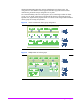
Scan for Storage and Confirm Available Space To access LUNs on supported devices within the SAN: 1. Select Storage Array Summary. 2. Select Actions > Scan for New Storage. The LUNs assigned to the HP NAS 8000 within the SAN will be added to the Storage Array Summary table. Figure 11 Scan for New Storage 3. Compare the figure in the Unallocated column to the available space on your planning worksheet. 4.
Create Volume Groups 1. Select Volume Groups. 2. Select Actions > Create New Volume Group. 3. Enter a Volume Group Name, then assign space from available LUNs. Figure 12 Volume Group Settings Repeat steps 2 and 3 to create additional volume groups. Create File Volumes 1. Select File Volume Summary. 2. Select Actions > Create New File Volume. 3. Assign a File Volume Name and select Quota Management and Capacity Policy options. 4. Enter the Capacity of the file volume (in GB).
Assign Shared Access A single file volume or directory can be both a Windows share and a UNIX® export. To creating a Windows share: 1. Select Shares/Exports and highlight a file volume. 2. Select Actions > Create New SMB Share. 3. Enter a Share Name and define additional share settings. Figure 14 Share Settings for Windows To creating a UNIX export: 1. Select Shares/Exports and highlight a file volume. 2. Select Actions > Create New NFS Export. 3. Enter a Mount Name and define additional export settings.
8. Enable the Software Modules The HP NAS 8000 SAN solution includes the following software modules: ■ Virus scanning ■ Local backup agent (for use with the optional tape library) ■ Snapshots (for fast access to previous versions of files) Use the Applications Tab to verify that all software modules are installed and to enable them: 1. Select the Applications Tab to view a list of all installed software modules.
Next Steps Using the System The HP NAS 8000 is installed. Use the Command View NAS web interface to perform additional setup tasks and to maintain the system. The web interface lets you: ■ Configure additional settings. ■ Manage storage. ■ Monitor the system by viewing settings on the Status tab. ■ Use virus software, backup agents, and snapshots to protect your data. ■ Contact support, use diagnostic tools, and upgrade the server software.
5 Safety The HP NAS 8000 solution consists of a number of component items (servers, disk arrays, etc.). Each of these component items have been independently tested for regulatory approval. Refer to the Regulatory Information statements and Certificates of Conformity contained within the individual component manuals shipped with your system. Note Customers are not expected to troubleshoot individual components. Individual component manuals are included for reference purposes only.
Safety
6 Warranty and Support Warranty Information Standard Limited Warranty The HP SureStore NAS 8000 standard warranty includes the following: ■ Two-year limited warranty ■ Same day on-site service for certain repairs (not available in certain geographic areas*; see table below) See the Hewlett-Packard Hardware Limited Warranty on the following page for a complete description of the standard warranty.
Warranty Upgrades HP offers warranty upgrades to provide a higher level of response or repair time commitment for your HP SureStore NAS 8000. For more information on upgrading your warranty, contact your local HP sales representative or authorized reseller. Warranty Contacts U.S. and Canada For hardware service and telephone support, contact: ■ An HP-authorized reseller or ■ HP Customer Support Center at 970-635-1000, 5 AM to 5 PM, M-F; outside the U.S., go to www.hp.
Hewlett-Packard Hardware Limited Warranty HP warrants to you, the end-user Customer, that HP SureStore NAS 8000 hardware components and supplies will be free from defects in material and workmanship under normal use after the date of purchase for two years. If HP or Authorized Reseller receives notice of such defects during the warranty period, HP or Authorized Reseller will, at its option, either repair or replace products that prove to be defective.
Warranty and Support