HP AA NetServer 4000 Reference Guide Printed in March 2000
HP NetServer AA Notice The information contained in this document is subject to change without notice. Hewlett-Packard makes no warranty of any kind with regard to this material, including, but not limited to, the implied warranties of merchantability and fitness for a particular purpose. Hewlett-Packard shall not be liable for errors contained herein or for incidental or consequential damages in connection with the furnishing, performance, or use of this material.
AA 4000 Reference Guide Contents CHAPTER ONE ~ARCHITECTURE OVERVIEW AND TERMINOLOGY..........................................1-1 What is HP AA?................................................................................................................................1-2 HPAA Components...........................................................................................................................1-3 Software Components ..........................................................................
HP NetServer AA Utilities........................................................................................................................................... 3-13 Display Software Revisions ............................................................................................................ 3-14 HP TopTools Remote Control Card ............................................................................................... 3-15 HP TopTools and Agents..............................................
AA 4000 Reference Guide Network Backups .............................................................................................................................6-4 Configuration Comparisons .............................................................................................................6-5 Backup Confiurguration Setup Notes ...............................................................................................6-6 Pure-local backup configuration ......................................
Ch 1: Architecture Overview and Terminology Chapter One ~ Architecture Overview and Terminology This chapter contains a brief overview of the HP AA system based on the Endrance 4000 software from Marathon Technologies.
HP NetServer AA What is HP AA? HP AA is a platform of high-availability solutions offering the highest levels of system uptime with the lowest total cost of ownership in the industry.
Ch 1: Architecture Overview and Terminology HPAA Components There are four major hardware componenets of the HPAA system: Network Server Division • The NetServers – Four NetServers are needed, two perform a synchronous operation of the NT operating system and the other two perform asynchronous I/O operations. • Marathon Interface Cards (MIC) – Each NetServer has a MIC placed in a particular PCI slot. The MICs are identical and all of them must have the same firmware revision levels.
HP NetServer AA Software Components Though at first glance, the HPAA solution appears to be mostly a hardware solution, in fact, it is an “85%” software solution. There are two major components of the software: the firmware on the MICs and the AA 4000 software installed on each of the NetServers. This obviously does not count the Windows NT operating system and any application software to be added for operation.
Ch 1: Architecture Overview and Terminology place only through AA 4000 Management Tools or Utilities. The Logical Server Logical servers are created from an array of four separate servers. Computing is distinctly separate from the input/output (I/O) processing, and the array runs simultaneously on two symmetrical halves (or tuples), which, combined together, do not have a single point of failure. I/O processors run asynchronously, and the compute elements run synchronously in lockstep.
HP NetServer AA allowing for the fail through performance should anything happen to one of the CEs. I/O Processors The other two NetServers take the roles of I/O Processors (IOPs). Within the AA 4000 software the IOPs are numbered IOP1 and IOP2. An IOP performs all I/O operations on behalf of the CE. It contains the hard disk drives necessary for storing its own copy of Windows NT, the CE’s copy of Windows NT, the applications installed on the CEs (applications for the array), and all of the needed data.
Ch 1: Architecture Overview and Terminology The term tuple simply refers to the pair of one CE and one IOP connected through one SSDL. Tuples are important during installation and when trying to determine the status of the array. By default, CE1 attempts comminucation with IOP1 first, and then IOP2 in the event of IOP1 being unavailable. However, even though the CEs try to communicate within their own tuple first, cross-tuple communications will occur when one of the NetServers is unavailable.
HP NetServer AA Windows NT and Application Licensing The HPAA based on the AA 4000 software requires four Windows NT licenses. The CEs must have two licenses of Windows NT Server or Windows NT Enterprise Edition and the two IOPs must have two licenses of any of the Windows NT products (technically, the IOPs will work with Windows NT Workstation). Given these parameters, it is recommended to have four Windows NT Server licenses.
Ch 1: Architecture Overview and Terminology Division of Labor The compute elements and the I/O processors have very distinct roles and therefore have different performance characteristics. If the array was going to do nothing more than run Windows NT without any applications, then the memory requirements are minimal. The array can be functional with 64 MB of memory for each node.
HP NetServer AA Client Network Access The HPAA System provides client network access to one logical server. As a single logical server, the system can provide services and applications to clients just like any other NT Server. However, the implementation of the network hardware and software is different than a single server environment. The I/O Processors have all of the needed network interface cards installed for the solution.
Ch 1: Architecture Overview and Terminology SCSI Identifiers During the installation and maintenance of the HPAA system, there are several different pieces of configuration data that must be collected, documented, and referenced. One of the more important pieces is the SCSI identifier for the logical drives that the AA 4000 software will “redirect” to the ownership of the CE.
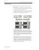
HP NetServer AA Here is an example of the SCSI information needed from the Windows NT Registry: When filling out the SCSI configuration chart included in the Installation Guide, the following notes are some reminders about the configurations of SCSI devices: • SCSI Bus Numbers – Be sure to have all of the drivers installed for the SCSI adapters to be used. The check the NT registry for the bus numbers. • SCSI IDs – Verify what SCSI ID is being used by the adapter.
Ch 1: Architecture Overview and Terminology To prevent this problem from occurring, you must change the default load order used by Windows NT. Changing the Windows NT default load order for SCSI adapter drivers requires modification to the Registry. Each adapter driver has a Registry key located at: \HKEY_LOCAL_MACHINE\System\CurrentControlSet\Services\% adapter_driver_name% (Where %adapter_driver_name% is the name of the SCSI adapter driver’s Registry key.
HP NetServer AA Device Redirection With the disk and network resources existing on the IOPs, but “owned” and accessed by the CEs, the AA 4000 software has to have a way to make this happen. The method is called device redirection.
Ch 1: Architecture Overview and Terminology The keyboard and the mouse connected to the IOPs are automatically redirected to the CEs when they boot. Control of the keyboard and mouse can be switched back to the IOP or to the CE by pressing . The HP AA 4000 Configuration Utility is accessible through the Start, Program, and HP AA 4000 menus on each of the IOPs. It is automatically installed as part of the AA 4000 software install.
HP NetServer AA Putting it all together Before the conclusion of the chapter, the following is a review of all of the AA 4000 components and how they work together. Using the diagram below, the best way to understand how the system works, is to trace a typical client transaction with the HPAA system. 1. The client requests (for example) to perform a databse query. 2.
Ch 1: Architecture Overview and Terminology synchronous. At the IOP level, due to the different spin rates of the disk drives, the I/O is asynchronous. The query results are eventually gathered by the CE (remember, the CE is running the SQL server application, not the IOP) and passed by both CEs to the SSDLs. The SSDLs both pass the network packet to the IOPs for transmittal. And at the last instant, only one IOP places the frame on the wire. The second IOP holds off so as to avoid Ethernet collisions.
HP NetServer AA NetServer Rackmount Configurations So far the diagrams used to describe the HPAA system have shown the NetServers out of the rack to help illustrate the components and their functions. The following is a look at the different configurations available when ordering the HPAA system. NOTE These configurations are specifically for the AA 4000 and are as of 3/2000.
Ch 1: Architecture Overview and Terminology NetServer LPr as the CE and the IOP Network Server Division 1-19
HP NetServer AA Rules for maintaining availability There really is only one rule when working with the HPAA system: Always maintain the highest level of availability. How is this done? Here are a few simple reminders to adhere to when working with or adminstrating the HPAA system: 1-20 • Never shutdown the “server” with clients attached. • Anytime one IOP goes offline for any reason while the CEs are in operation, a disk re-mirror operation must take place after the IOP is brought back online.
Ch 2: HPAA System Boot Up Chapter Two ~ HPAA System Boot Up This chapter covers the startup process for the HPAA system. Before going through the details of powering on the system and beginning to use it, the proper hardware connections should be verified. In the event there is a problem with the basic connections, how to use the MTCTEST utility ti troubleshoot will be covered first.
HP NetServer AA Verifying the MIC connections Before booting the system, a quick visual verification of the connections between the MICs and the SSDLs should be performed. A more through verification can be performed using the MTCTEST utility. It is important to make sure the MIC connections are good before powering up the system and re-checking the connections when a failure of any type occurs in the system.
Ch 2: HPAA System Boot Up IOP to the SSDLs (1 and 2). The last row labeled “link” is for the connection between the SSDLs. When the SSDLs are not powered (not plugged in), the LEDs are completely off. On the far right of the front of the SSDL are power indicators; one for each power cord that can be used (the SSDL has two power inlets for redundancy, only one is required).
HP NetServer AA Troubleshooting a “RED” LED When an LED is Red on the SSDL, the problem is the MIC cable, the port it is plugged into, or the MIC itself. Troubleshoot this situation as follows: Disconnect the cable at the point where the LED indicates there is a problem. For example, if the LED that interesects column 2 and the “compute” row is red, then remove the cable from the MIC card on CE2. Check the pins on the cable and the port on the MIC.
Ch 2: HPAA System Boot Up MICs must be used meaning the MTCTEST must be run on two NetServers simultaneously. NOTE Create two utility diskettes for easier testing. Before running the MTCTEST verify: • All MIC cables and the tuple link cable are securely attached. • The tuple ID LED buttons are correct on each SSDLl. • The SSDL is powered on and all SSDL LEDs are green MTCTEST confirms the following: • The server can identify and access the local MIC registers and RAM spaces over the PCI bus.
HP NetServer AA • Test 3: Verify Host < - > MIC DMA - Verifies the integrity of the Host-to-MIC PCI interface by accessing DMA, RAM, and runtime registers. Simulated MIC messages are transferred through the MIC and looped back to the host where they are verified for integrity. Failures in this test typically indicate a problem with the DMA engine on the host or MIC adapters. The DMA test completes after approximately one minute.
Ch 2: HPAA System Boot Up Powering Up the HPAA System There are up to eight components that need to be powered on in order to use the HPAA system (not counting any UPS devices in the rack): • Four NetServers • Two SSDLs • Console Switch Box • Monitor Before examining the power on sequence, first take a look at a typical rack implementation and how it is cabled from the perspectives of AA 4000 hardware, the console switch, and power.
HP NetServer AA overtighten, as this will potentially break the screw, or cause the screw to be stuck and the cable cannot be easily removed. Recommended Cabling Order When installing the ribbon cables, the following order is recommended: 1. Connect the CEs to the SSDLs (5 feet cables) 2. Connect the IOPs to the SSDLs (5 feet cables) 3. Connect the SSDL Link (5 foot cable with ferrites) 4. Connect the IOP Link (Patch cable) Do not force any cable connections or overtighten cable screws.
Ch 2: HPAA System Boot Up the viewing of both CEs and IOPs. The HP Console switch has specific cabling requirements. To correctly cable the HP console switch within the array, use the following steps. 1. Verify the Monitor, Console switch, and keyboard kit have been rack-mounted 2. Gather the necessary peripheral cables 3. Connect the keyboard, mouse, and monitor to the Console Switch 4. Connect Console Port 1 video to the SSDL for Tuple 1, the keyboard to IOP1, and the mouse to IOP1 5.
HP NetServer AA outlets to go to each tuple as pictured above. One of the PDUs will have to be used for the video monitor. NOTE If four NetServer LH4s are rack-mounted in a single cabinet, four PDUs are required. UPS systems are highly recommended and should be used for each PDU. For the optimum in power protection, AC sources should be from different circuits, different phases, and different transformers to two UPS systems and then to the rack to the extent possible.
Ch 2: HPAA System Boot Up logs, and start troubleshooting. Once the IOPs are joined then it is time to power on the CEs. 3. Power on CE1 – Only power one CE at a time. As CE1 is powered on, the POST and boot operations can be watched by changing the console switch and SSDL. Shortly after the MIC is detected in CE1, watch the Marathon Manager on one of the IOPs to see the color changing sequence of CE1 while it is booting into Windows NT.
HP NetServer AA AA 4000 Boot Options When powering on the IOPs and watching the boot process, the Windows NT Boot Menu will appear. The boot menus may look slightly different on each IOP because Windows NT was installed twice on IOP1 and there are legacy Windows NT boot options. The first three entries in the Windows NT boot menu are created during the installation of the AA 4000 software.
Ch 2: HPAA System Boot Up AA 4000 Boot Process The CE and IOP boot process are independent of each other with the exception that the CE’s cannot start their boot sequence until at least one IOP is available. If a CE is powered up before an IOP is available, the screen of the CE(s) will display a text message that the Marathon boot is in progress on a black screen. It will stay this way until one IOP is in Marathon Operational Mode and the IOP has checked up on the other IOP.
HP NetServer AA Detailed Boot Steps - IOPs When in doubt about what component is failing, watch the AA 4000 boot process from POST of the server to the POST of the system, and at the same time, look at what the error logs are recording, and watch the Marathon Manager console. Follow it along to make sure each step is getting completed, and if not find the component preventing any of the steps.
Ch 2: HPAA System Boot Up Using the Keyboard, Mouse, and Video Once the HPAA system is powered up and all the NetServers are in the array, it is important to always make sure when using the keyboard and mouse that it is in the correct “context” of the NetServer. And it is important to make sure the video displayed is for the NetServer expected. Video This is the easiest to keep in correct context. By default when the AA 4000 software is installed, the backgrounds of the desktops on both IOPs are changed.
HP NetServer AA Using One Monitor Using two monitors is not practical, especially in a rack mount environment. One monitor cabled to a console switch allows for the viewing of any of the four servers. The SSDL video switch is still used, so there are essentially two switches that have to be used in conjunction with each other. To view any of the servers: 1. Use the HP console switch to choose one of the Tuples by hitting the PrintScreen Button and selecting Port 1 for Tuple 1 and Port 2 for Tuple 2.
Ch 2: HPAA System Boot Up SSDL for the tuple being accessed and then press to gain control of the keyboard and mouse.
HP NetServer AA Shutting Down the System There are various methods to shut down the system, power down the system, or remove a component from the array. It is imperative that the administrator understands what the goal is before issuing a command to the system that removes the component or shuts down the system.
Ch 2: HPAA System Boot Up For more information on using MTCCONS, see the AA 4000 Users Guide. Removing Components Most components of the HPAA system can be removed from participating in the array. The advantage of being able to take this step is to proactively remove a component for maintenance that will prevent the AA 4000 software from reporting the same errors again and again, or worse, “failing” the component out of the system.
HP NetServer AA without it). For a disabled IOP to rejoin the array issue an IOP Enable Operation command. Before disabling an IOP, verify that: • The IOP to be shut down is not marked as the source of a mirror copy. • Make sure that the other IOP is active. • If possible, perform any necessary backups for non-mirrored devices on the IOP to be shut down. • Make sure that the other IOP has public network connectivity (IOPx.Ethernet cable is online).
Ch 2: HPAA System Boot Up Server Shutdowns and Reboots By now, it is apparent that MTCCONS or the Marathon Manager can be used to change the status of a component or the entire system. Server shutdown commands are no different. The most important aspect of a server shutdown to note is not the command to execute a shutdown, but instead knowing how to perform an actual shutdown and not just a reboot. Whenever a ‘shutdown’ command is issued, the array will attempt to reboot.
HP NetServer AA Using the “Right” Copy of Windows NT The HPAA system features three distinct installations of Windows NT in operation; one each for the IOPs and one for both of the CEs. Remember, the CEs operate in lockstep and use the same copy of Windows NT. Regardless of which CE is being viewed based on the tuple choice, any modifications made to Windows NT on the CE occurs once, but it written to two different disks on each IOP for redundancy.
Ch 2: HPAA System Boot Up properties of NT, the administrator can join the NT domain as normal. Network Server Division • Setting up security – Whether the CE remains as stand-alone server or joins an NT domain structure, security precautions must be taken.
Ch 3: AA 4000 and HP management Tools Chapter Three ~ AA 4000 and HP Management Tools Mangement of the HPAA system is made easy by the use of the Marathon System Management Utility (MSM) or “Marathon Manager” for short. This tool can be run on any of the systems in the array or on a client. Other management tools available are from theHP suite of management tools. However, there are some limitations.
HP NetServer AA AA 4000 Software Architecture The main value of the HP AA 4000 software is its ability to “split” the Windows NT architecture and allow the IOPs to function as the I/O agents of the CEs. Looking at the array as a whole and the Windows NT architecture, what is in effect happening is the CEs are operating in User mode and the IOPs are operating in Kernel mode.
Ch 3: AA 4000 and HP management Tools Network Server Division • Marathon Transport – This handles all data movement within the array where the redirectors and providers are concerned. It works in conjunction with a Device Synchronization Layer to make devices appear as one to the CEs and move the data using Marathon Interface Cards (MICs). • Monitor – This is in charge of all state transitions, reports status to the Marathon Manager, and executes various Marathon manager commands.
HP NetServer AA Marathon System Manager (MSM) The Marathon System Manager (MSM) is a GUI-based tool which runs on the local copies of NT Server within the array or on a NT Workstation client. In either case, Administrative equivalent access to the NT Servers is necessary to manage the array. This permission would be set in the User Administration Tool of the CE. The MSM is the primary tool for array management and status monitoring. All activity in managing the array starts with this tool.
Ch 3: AA 4000 and HP management Tools Remote Management The Marathon Manager can be installed on a remote workstation to administer the AA 4000 array. Connection can be done using either a local area network or a modem. After installing the Marathon Manager and establishing the remote connection, the administrator can use Marathon Manager features and options to administer an AA 4000 array.
HP NetServer AA MSM – Main Screen Upon installation, the Marathon Manager is available through the Windows NT Start button > Programs > Marathon > Marathon Manager, or, Start > Run and type mtcmgr. When launching at the CE or the IOP, the MSM will automatically connect to the local array. The MSM has the ability to manage remote arrays by typing in the server name in the lower right-hand corner and clicking on the update button.
Ch 3: AA 4000 and HP management Tools Control and Display From the tools menu is the Control and Display window that acts as a command initiator window. This screen is also available by double clicking on a component in the Administration menu. The window displays the commands, options, and parameters that allow for array management and the displaying of detailed component status and configuration information.
HP NetServer AA Control and Display Options 3-8 OPTION DESCRIPTION Command Description When a command is selected, this area displays a brief description of the command. Filters Applies a filter to the target field to display subsets of the various components. Target List the available components on which commands can be performed. For each command selected, a target must be selected. Operation Displays the components available for the selected action to be performed.
Ch 3: AA 4000 and HP management Tools MSM Preferences From the tools menu, select options to get to the preferences screen. This screen configures the monitoring parameters. The time in seconds between updates can be set for the Administration window through polling and the time can be set for refreshes of any windows displayed as a result of the show command. The setting of 0 seconds will disable any automatic updating.
HP NetServer AA Device Status The device status screen can be seen as part of the main administration view. It will not be seen as the default when launching the MSM. To view the status screen as a separate window, check the appropriate box in the preferences (options) screen.
Ch 3: AA 4000 and HP management Tools The following is a color legend to help interpret the status of each component: Color Component Indicates Blue All Booting* or Joining* Blue-Green All Ready Dark Green Ethernet Adapters Standby Interconnects Online SCSI Disks Destination disk of a mirror Keyboard / mouse Online, but in arbitration All others Initialized* Dark Grey All Disabled Light Green CE’s, IOP’s.
HP NetServer AA Last Mirror Copy Status Just like the Device Status window, the mirror copy status window appears on the main administration view by changing the preferences (options). Because this window displays the last mirror copy status from a particular IOP, it is possible for the IOPs to return last mirror copy status reports that appear slightly different. Any IOP that is actively serving the CEs (it is online) will provide complete and current mirror copy status reports.
Ch 3: AA 4000 and HP management Tools Utilities From the Tools menu, the administrator can access commonly used Windows NT utilities. The NT utilities available are: • Control Panel • Disk Administrator • Event Viewer • Explorer • File Manager • Notepad • Performance Monitor • Registry Editor The Tools menu also provides access to the Marathon Configuration utility and a Marathon Event viewer / utility.
HP NetServer AA Display Software Revisions From the View Menu, the Revision Levels of the various software components can be seen in one central location. The software revisions displayed are from the perspective of the IOP of run on the IOP or of the CE if run on the CE or from a client workstation. The screen is useful when collecting data about software updates / patches, firmware revisions, and the Marathon Kit number.
Ch 3: AA 4000 and HP management Tools HP TopTools Remote Control Card HP NetServer AA Solutions have powerful and intelligent management tools. HP TopTools Remote Control Card, which comes standard in enterprise-class HP NetServers and as an option for most other HP NetServers, conducts efficient remote management and transmits basic device information to HP TopTools, through Microsoft Internet Explorer. Currently, this tool is supported on the CEs and IOPs in the array.
Ch 4: Networking Explaineds Chapter Four ~ Networking Explained Given the fact that the HPAA system provides application services to the network, it is very important to install and configure the network components correctly. There are three different network types at work when using the HPAA system. Though all three networks use standard networking properties in Windows NT, their configurations differ slightly.
HP NetServer AA Network Planning Before installing and configuring network adapters it is important to plan the networking environment in order to determine the number of network cards needed, the PCI slots they are installed in, which subnet they will be connected to and the necessary networking protocols. Most of the network planning and configurations of the network cards may have been done as part of the initial order of the system.
Ch 4: Networking Explaineds Windows NT Bus Numbering Network services, protocols, and bindings will have to be configured as part of the software installation. Working with multiple network cards and configuring software parameters can sometimes be confusing when mapping the physical slots to what the operating system displays. It is imperative that the relationship between physical slots and Windows NT slot numbering is known.
HP NetServer AA Gathering Networking Information In order to successfully configure the network cards, gather the following information: • MAC addresses • PCI Slot location • Subnet attached to / planned TCP/IP address This information will be used to configure the network cards in the Marathon Configuration Utility and the Windwos NT Network Propeties. Three Independent Networks There are three distinct network types in operation for any implementation of the HPAA Solution.
Ch 4: Networking Explaineds The Private Network (IOP link) As mentioned earlier, the IOP Link is a private network for the IOPs to monitor each other and transport data for mirror copies. The network is essentially a two-node Ethernet network directly connected by a CAT5 UTP crossover cable, or connected via a hub or switch in SplitSite configuration. Gigabit Ethernet is also supported as a network medium for the IOP link. The most important aspect of the IOP link is the network parameters.
HP NetServer AA Before any Marathon software implementation is performed, two pieces of data need to be collected: (1) the MAC addresses of the network cards to be used, and (2) the verification of the PCI slot use. Armed with the above information, the protocols and services can be set up on known, good equipment. The bindings to be deployed as part of the Network card configuration are a traditional networking protocol of choice (NetBEUI, TCP/IP), the MtcEtx Driver, and the Marathon Datagram Service.
Ch 4: Networking Explaineds The Public Network (Ethernet Rails) A pair of network cards, one in each IOP, in the same PCI slot numbers constitutes a “public rail.” There are several different terminologies used for essentially the same network type. For the network cards that the IOPs use to intercept client traffic on the network, these cards may be referred to as the public network, a public rail, or an Ethernet rail.
HP NetServer AA onward if the first NIC fails. The CEs will then generate a series of requests to be carried out by the resources of the IOPs. When the transaction is completed by the CEs and both CEs send the result to the SSDLs, the IOPs will then prepare to generate LAN traffic, but only one NIC in each rail is the responder or traffic generator directly on the LAN.
Ch 4: Networking Explaineds IOP Public Rail Bindings Each pair of network cards on the IOP will have the same bindings. Each physical network card will NOT be bound to a traditional protocol. Instead, each network card will only have the Marathon Datagram Service and the Marathon Ethernet Provider as its only enabled bindings. Along with the traditional protocol, the MtcEtx protocol will be disabled. Public Rail Configuration (CE) The bindings on the CE will be a little different than the IOPs.
HP NetServer AA The adapter that works in conjunction with the public rail is the MTCETHR Virtual adapter. This adapter is an Ethernet Redirector and is “matched up” with the pair of adapters in the IOP, which are bound to Ethernet Providers. To logically follow the path, the IOP, being the system with a NIC directly on the LAN “provides” network capabilities. The CE accesses this capability by “redirecting” networking requests to the IOP. Still, there is no direct communication from the CE to the IOP.
Ch 4: Networking Explaineds segment B via a different path, then the MTCETHRs need to reflect that in their addressing. The bindings to each MTCETHR consist of the appropriate traditional network protocol. Public Network to IOP to CE and Back. Now that all of the protocols and bindings are in place, a “trace” of a typical network request can be traced through the tuple. 1.
HP NetServer AA The Virtual Network As mentioned earlier, each IOP and CE will have a virtual network adapter for the purposes of creating an internal network in the array. The virtual adapters are not associated with a physical network card. Any use of the virtual network or traffic generated will be carried out by the MICs and the SSDLs. This network helps facilitate access to resources throughout the array for maintenance purposes. It is not used to facilitate client traffic to the LAN.
Ch 4: Networking Explaineds The remaining Marathon services are disabled for the virtual adapters. There is no need for the Marathon Datagram Service, the Marathon Ethernet Provider, and the MtcEtx driver. The virtual adapters themselves are slightly different between the CEs and the IOPs. The IOPS use a virtual provider (MtcVnP) and the CEs use a virtual redirector (MtcVnR).
HP NetServer AA Adding a Public Rail After the HPAA system is operational, it may be decided that another public rail is needed for whatever reason. It could be to offload traffic from one public rail and have more aggregate bandwidth, or it could be to service clients from a specific LAN segment. There are two choices of methods to add a public rail. One choice places the emphasis on uptime and will only have one single system reboot.
Ch 4: Networking Explaineds Network Server Division • The IOPs have the actual HP 10/100 TX driver installed and it is listed in the network properties in Winodws NT on the IOP even if the network cards are being redirected. Through the protocol “Marathon Ethernet Provider” it establishes a relationship with a MTCETHR virtual adapter on the CE. • The CEs only have virtual adapters, one MTCETHR virtual adapter exists for each public rail.
Ch 5: System Upgrades Chapter Five ~ System Upgrades This chapter contains information on system upgrades for the HP AA system based on the Endurance 4000 software from Marathon Technologies.
HP NetServer AA Before Upgrading the HP AA System Adding components to an existing HP AA Array is not as simple as adding components to a standalone system. Many considerations must be taken into account to ensure the array experiences no downtime or at least the minimum downtime necessary for the action. One of the primary considerations when performing many system upgrades is the decision to maximize uptime in lieu of a disk remirror or sacrifice the downtime to avoid a disk re-mirror.
Ch 5: System Upgrades System Documentation The Endurance 4000 Installation Guide contains system documentation tables designed to assist in the accumulation of data necessary for installation and maintenance of the array. This information is a good starting place when seeking to become familiar with the array. Once the array is properly documented the upgrade process can begin.
HP NetServer AA Adding Additional Storage to the Array During the life cycle of any Server system there is a high likelihood the storage space will need to be increased. Adding storage to the Endurance 4000 array is not a difficult process but there are a few areas where care must be taken. When adding storage to the Endurance 4000 the first question that needs to be answered is "Can downtime be tolerated?" The answer to this question will determine the procedures taken to add the storage.
Ch 5: System Upgrades installation of the Marathon array and should still be available. If not, take the time to document it now: • How many physical drives are present in the LH3 or LH4.
HP NetServer AA The Disk Administrator is used to create the partitions on the new drive. Make sure to create the special Marathon partition at the end of the drive. Do not format this partition or assign a drive letter to this partition. All partitions other than the Marathon partition must be formatted NTFS. If the other IOP is not being configured at this time make sure to document the partition structure for duplication on the other IOP.
Ch 5: System Upgrades This is the point where previous documentation comes in handy. By comparing the previous 4 digit SCSI IDs with the IDs displayed in the Registry it should be easy to pick out the new ID. Record the new ID for future use. Make sure the other IOP has the same 4 digit SCSI for the new device. Modify the Marathon configuration on IOP1 and IOP2 Once the 4 digit SCSI ID has been acquired the Marathon Configuration Utility can be run to add the new mirrored storage.
HP NetServer AA Before adding the additional storage After adding the storage.
Ch 5: System Upgrades The best method for modifying the Marathon configuration is to make the modifications on one IOP, save it and copy to the other IOP. Reboot the array At this point everything is ready. A final reboot of the entire array is necessary for the disks to be redirected to the CEs. Confirm the new drives on the CE Open Windows Explorer and examine the new drive. Adding SCSI Devices (HBA's, HP NetRAID) Since this operation requires the installation of hardware the IOP must be brought down.
HP NetServer AA The following table should be followed when installing additional devices.
Ch 5: System Upgrades Upgrading the Marathon Software If the Marathon software needs to be upgraded or “patched”, there are several considerations. Before upgrading Marathon software, make sure that: • The Marathon CD that contains the new version of software is available • An MTC diskette made using the new Marathon software is done • All mirror copies are done. • There is up to 24 MB of free space on the each IOP and CE system drive.
HP NetServer AA Upon completion of flashing all MICs, the array can then be restarted and the Marathon Manager can be used to verify the array is completely operational. Upgrading Marathon software on the CE Operating System Considerations for upgrading the CE Operating System: • A CDROM must be available to the CE either by way of a redirected IOP device or a shared IOP device. • The Marathon installation procedure will start automatically unless the auto launch feature has been disabled on the CE.
Ch 5: System Upgrades • Install Endurance Software • Kit Number • IOP installation • Restore Original Installation Parameters • IOP in TUPLEx (for IOP1, choose TUPLE1; for IOP2, choose TUPLE2) • Destination directory for IOP Maintenance Mode • DoNot Edit Configuration • Install the Endurance 4000 online documentation. • If you are running Windows NT Server on the IOP, configure the Network, Service, Server, and Properties to Maximize for Network Performance.
HP NetServer AA Verifying the Upgrade After upgrading Marathon software, use Marathon Manager to make sure that: • All Endurance components transition to active, online or standby (either bright green or dark green). • Any required mirror set copies are in progress or have completed successfully. • The revision information (displayed using View->Revision Level) is identical to the revision information documented in the Endurance 4000 Release Notes for newly installed software.
Ch 5: System Upgrades Upgrading an Installed System to an SMP IOP System Having dual processors in the IOP is overkill for the array workload. The IOP is responsible for the I/O activities which are not processor intensive. During installation it is better to install the multi-processor kernel even if a single processor will be used. This will not affect the installation of the Marathon software and will eliminate the need to upgrade the kernel when an additional processor is added.
HP NetServer AA Updating/Patching Windows NT with Service Packs The HP AA array is able to have different Windows NT Service Packs on each system of the array. The only consideration is that the Service Pack must be supported. Examine the Readme file located on the Marathon CDROM for the supported Support Packs. One reboot is required for a Service Pack upgrade of all systems. If only the IOPs will be upgraded they can be done one at a time with re-mirrors in between.
Ch 5: System Upgrades Updating NT Applications The key to upgrading NT Applications is to make sure the upgrade is performed on the proper machine. All array applications run on the CE operating system. Generally, applications are upgraded using a CDROM. Since the CE does not have it's own CDROM, a redirected CDROM must be used. An alternative to this method is to use a Network Shared CDROM.
Ch 6: Backp and Restore Chapter Six ~ Backup and Restore Even though the HPAA system provides an unprecendented level of availability for Windows NT, it does eliminate the needs for backups. Even if the HPAA system never went down in two years, it would be nice to have a backup simply for disaster recovery situations in those rare occurances.
HP NetServer AA Backup topologies and tradeoffs There are many backup topologies one might consider for backing up HPAA systems. To help system administrators configure and setup backups HP recommends three topologies: • Pure-local backup configuration • Semi-local backup configuration • Network backup configuration Pure Local Backups This configuration uses a HP SureStore TapeRack with two DLT 70r tape drives and two DAT 24r.
Ch 6: Backp and Restore NOTE "Autoloader" tape devices for local backup are not supported at the time of this writing. Backup software, such as Veritas Backup Exec 7.3 or Computer Associates ArcServe IT 6.61, is installed on the CE and run on the CE. Backup software backs up the CE NOS disk and the data disks in the same manner as in a standard (standalone) system.. Semi-Local Backups In this configuration, only two tape backup drives are used.
HP NetServer AA Network Backups In this configuration all backups (CEs and IOPs) are performed over a dedicated backup network. A redirected pair of network cards is configured as a “public LAN” through the Marathon Configuration Utility, but instead of being used for client network access, it is recommended the NICs attach to a switch. The switch will be part of a separate LAN for the purposes of performing backups.
Ch 6: Backp and Restore The IOPs will have one NIC each that is not redirected and will be connected to the same switch for the network backups. In this configuration, the backup software backs up the CE and the two IOPs as three individual systems. Configuration Comparisons The following table lists the factors of tradeoff among the three configurations: Local Backup Semi-Local Backup Network Backup Backup Performance Gives best backup performance. Slowest of the backup performance.
HP NetServer AA Backup Confiurguration Setup Notes The following are some important recommendations when setting up each of the different backup configurations. Additional information on SCSI IDs and settings can be found in Chapter One of this guide or in the AA 4000 Installation Guide. Pure-local backup configuration • The DAT and DLT tape drives can share the same SCSI channel. NOTE The SCSI ID of each device must be set properly.
Ch 6: Backp and Restore • An alternative method to backup each IOP is to use a dedicated NIC configured in each IOP for performing a CE controlled network backup over the public CE network connection to the dedicated backup network connection of the IOP. Below is the network backup configuration for setting up a dedicated IOP network connection. 1.
HP NetServer AA Enable - Marathon Datagram Services Enable - Marathon Ethernet Provider Disable - MTCEtx driver 2. Configure a unique IP address for each dedicated IOP network connection. 3. Next, go to the CE Network Properties, and change the bindings on both Marathon MtcVnR to the following.
Ch 6: Backp and Restore • The CE and the two IOPs are configured as three individual backup clients. • The dedicated IOP and CE network cards are configured as below. 1. Install the new NIC cards and add the NIC adapter driver. 2.
HP NetServer AA Enable - Marathon Datagram Services Enable - Marathon Ethernet Provider Disable - MTCEtx driver • New Network Adapter (for dedicated backup CE network) Disable - NetBEUI Protocol Disable - TCP/IP Protocol Disable - Wins Client (TCP/IP) Enable - Marathon Datagram Services Enable - Marathon Ethernet Provider Disable - MTCEtx driver 3. Configure a unique IP address for each dedicated IOP NIC. 4.
Ch 6: Backp and Restore Disaster recovery procedures In the event of a disaster or an operator's error, it is possible that the CE OS can be put in an inoperable state. When this occurs it may be possible to recover the system without restoring from backup tapes. Below is a set of procedures to assist system administrators to recover systems with minimum downtime. The procedures must be followed in order listed below. 1.
HP NetServer AA 2. Minor Repair Using An IOP In Off Line Mode Use an IOP in offline mode to invoke the repair to the CE BOOT disk - then force a mirror copy in the proper direction as you recover. The steps are: a. Choose an IOP to undertake the repair on the CE BOOT device (cannot be the unfinished target of a mirror copy) b. Reboot the selected IOP to MARATHON OFFLINE MODE (the server already is down/cannot be rebooted - or you would repair it from the running CE OS). c.
Ch 6: Backp and Restore is a significant change to the CE, a new backup copy needs to be made using the MTCCPYNT.EXE. Otherwise, the backup directory created by the utility becomes out of date. A recovery from the saved data should be upgraded with the latest back up (of the system disk). The steps to implement this scheme are included below: a. PERIODICALLY CREATE AN EMERGENCY RECOVERY COPY of your CE OS b. Determine the pathname where mtccpynt.
HP NetServer AA 4. TO RECOVER the CE OS USING AN EMERGENCY RECOVERY COPY The CE is down already (it cannot be booted, due to the problem we are recovering from). Perform the following: a. Choose the IOP best suited to support the recovery and reboot it into Marathon Off-line Mode. (Choose an IOP that is known to have a good copy of the CE BOOT DISK.) b. Determine the drive letter where the CE OS resides. (D: for purposes of the following discussion). c.
Ch 6: Backp and Restore Part Numbers for Backup Configurations Pure-local backup • C5695A - HP SureStore TapeRack for HP 19” server rack, includes one 0.9m SCSI cable, two 2.5m SCSI cables, and two SCSI terminators (Tape Rack holds 4 tape devices –see below). • C5698A - HP SureStore DLT 70r (need two - 1 on each IOP). • C5696A - HP SureStore DAT 24r (need two - 1 on each IOP). • D5025A – PCI ultra-wide host bus adapter (one Adaptec AHA2940UW). • Backup Software - Computer Associates ArcServe IT 6.
Ch 7: Bsic Troubleshooting Chapter Seven ~ Basic Troubleshooting This chapter contains information on proper troubleshooting procedures and tools for the HP AA system based on the Endurance 4000 software from Marathon Technologies.
HP NetServer AA Overview of Troubleshooting in a HP AA Environment The HP AA system is a fault tolerant system. When faults occur (for example, a failed network adapter) the system continues to operate. While the system is operational, any additional failures to the faulted components redundant counterpart can affect the availability of the system. Returning the system to a state of fully fault tolerant consists of a series of actions.
Ch 7: Bsic Troubleshooting NOTE If you are monitoring the HP AA array using the Remote Marathon Manager, you only have access to the Marathon Manager and the Windows NT Event Viewer information. Other MTC Tools Marathon provides other tools with the system which are not necessarily troubleshooting tools, but they can be great for information gathering.
HP NetServer AA Isolating the Faults When first troubleshooting the array check the following in order: 1. Check each SSDL for the following: Status Lights Tuple ID Buttons Power Indicators The status lights in column 1 and 2 are green. A tuple button is lit and not blinking. Both power lights (one for each power supply) are green. In most cases it is safe to assume if the connection status lights are green then solid connections exist.
Ch 7: Bsic Troubleshooting connection does not exist. The best assurance of a good connection is the MTCTEST utility running packet transfers between MICs. The two devices participating in the test must be CE and IOP. While the test is being run, these devices cannot be participating members of the array. 2. Using the Marathon Manager Administration window and the Device Status window, note any components that are not active, online or standby.
HP NetServer AA will show a link down and in many cases a quick check of the cable connector may solve the problem. The Marathon cables are heavy and if not properly tightened can come loose to a degree that will cause a fault. 4. If the CE is active, check the Windows NT Event Viewer for Marathon caution or critical messages. Check the IOPs for the error messages, each IOP will vary from the other IOP. It is absolutely critical this tool be used to diagnose problems with the array.
Ch 7: Bsic Troubleshooting hardware problem. Remove the IOP and perform normal troubleshooting procedures. If there is a configuration mismatch between IOPs it will be reported here. MtcEthP IOPn.MtcEthP status If the IOP has insufficient memory, errors may occur here. IOP Ethernet subsystem events that occur between the IOP and the public Ethernet. Windows NT LAN driver problems will cause errors in this section.
HP NetServer AA Handler status IOPn.MtcMon FRU IOPn.MtcMon status Generally errors center around MIC to MIC transmission and cables. Failed MICs and SSDLs also show up under this section. Frozen systems and hardware errors resulting in a system crash will create events in this section. MtcScsiP IOPn.MtcScsiP status MtcScsiR None MtcSmR IOPn.MtcSmR status MtcVnP IOPn.
Ch 7: Bsic Troubleshooting • Hardware/Software Devices that may be faulted resulting in the event • Action: This section provides a list of remedies to the event. These actions should be attempted in the order they are displayed. • See Also: Pointers to additional information sources relating to the event.
HP NetServer AA match. Replacement components should also be placed in the same slots or bays that their predecessor came from including the cabling and other connectors. Providing Information to the HP Call Center Before notifying the Call Center have the following information available: • Status of any indicator LEDs on the SSDL, NICs, MICs, Servers and Hubs. • Status of devices as reported by the Marathon Manger • Event Log messages that are Warning or Error events.
Ch 7: Bsic Troubleshooting Basic Marathon Hardware Replacement Replacing the MIC Cable There are a number of components that can be affected by a failed MIC cable. The IOP or CE to which the cable is attached will be in a degraded state. Make sure to examine all components to make sure the failed cable is the only component that is bad. Once you have acquired a replacement cable, shut down the system where the cable is attached. Make sure you follow the proper shutdown procedures for the CE or IOP. 1.
HP NetServer AA 10. If any components are faulted or disabled, re-enable them using the appropriate Marathon Manager Enable command. 11. Make sure that a mirror copy is started. Replacing the IL Cable The IL (IOP Link) cable provides a direct Ethernet connection between the IOPs. To replace an IL cable: 1. Obtain a replacement IL cable from your service provider. The IL cable is a Category 5 Ethernet twisted-pair crossover cable. 2.
Ch 7: Bsic Troubleshooting 7. Issue a Marathon Manager Disable IOPy.Ethernet command so that you disable the Ethernet connection that maintained network connectivity while you completed the previous steps. 8. Issue a Marathon Manager Enable IOPy.Ethernet command for the Ethernet connection that was disabled. 9. Establish a network connection to validate that the connection is operating properly. For example, use Windows NT Explorer to connect to a network node. 10.
HP NetServer AA 7. Compare the MIC revision information reported during boot to the MIC revision required for your Endurance 4000 software (as noted in the Release Notes). If they do not match, run the MTCFLASH Utility to install the correct MIC firmware; otherwise, the system cannot join the Endurance 4000. 8. On each SSDL, make sure that the status lights in column 1 and 2 are lit green. 9. If one of these status lights is red or not lit, correct the condition and continue. 10.
Ch 7: Bsic Troubleshooting 9. Attach the cables to the SSDL. Make sure to attach the correct cables to the correct ports. Refer to the label step mentioned previously. 10. Attach both SSDL power cords to the SSDL and their power source. 11. Boot the systems. 12. On each SSDL, make sure that the status lights in column 1 and 2 are lit green. 13. If one of these status lights is red or not lit, correct the condition and continue. 14.
HP NetServer AA 2. Install LAN adapters, MICs, and any other cards, disks and memory. Make sure to match the removed IOP exactly. NOTE For the Ethernet adapter that provides network access -- If you removed this adapter from the IOP that you are replacing, do not use it in any other network device other than the new IOP. Otherwise, it can cause MAC address conflicts. 3. Decide which, if any, disks will be transferred to the new IOP.
Ch 7: Bsic Troubleshooting • Installing Windows NT • Installing Marathon software only for this IOP. • Using the Marathon Configuration Utility to make any appropriate changes to the configuration. If the configuration has changes, you must update the configuration on both IOPs. 10. Reboot the new IOP into Online Marathon mode. 11. Use the Marathon Manager to: • Make sure that any components affected by this procedure are active or online.
HP NetServer AA • Note MIC revision information is displayed to the screen during boot. • Compare the MIC revision information reported during boot to the MIC revision required for your Endurance 4000 software (as noted in the Release Notes). If they do not match, run the MTCFLASH Utility to install the correct MIC firmware; otherwise, the system cannot join the Endurance 4000. 12. On the SSDL, make sure that the status lights in column 1 and 2 are lit green. 13.
Ch 7: Bsic Troubleshooting 7. Replace the adapter with an identical adapter (the same manufacturer and the same model). NOTE If you cannot acquire the proper replacement, you must replace both adapters (one in each IOP). This requires removing the previous adapter (driver) and adding support for the new adapter. In this case, you need to acquire the appropriate Windows NT distribution and driver media, and schedule time to shut down the Endurance 4000.
HP NetServer AA • Issue a Marathon Manager Enable IOPy.Ethernet command for the Ethernet connection. • Establish a network connection to validate that the connection is operating properly. For example, use Windows NT Explorer to connect to a network node. • Using the Marathon Manager main window, confirm that the Ethernet connection that uses the replacement cable is active and primary.
Ch 7: Bsic Troubleshooting other words the adapter can now be used on the same network as the Marathon array. 13. Remove the file previously created. The new configuration is fully operational, and the backup file now contains obsolete configuration information. Replacing a Failed Mirrored Disk The following procedure pertains only to drives not protected under NetRAID. Drives protected under NetRAID can be replaced using the normal procedures for replacing a hot swap drive.
HP NetServer AA The re-mirroring process will overwrite everything. It is important the Marathon partition be at the end of the drive. 9. After the initial mirror copy completes, this disk will have the correct disk format, disk label, disk partitions, and disk data. Open the Marathon Configuration Utility and complete the following: 10. Save the current configuration to a file. 11. Remove the configuration entry for the disk to be replaced and select Commit.
Ch 7: Bsic Troubleshooting 4. When the NetRAID adapter boots a mismatch will occur between the disks and the NVRAM of the NetRAID adapter. When this occurs open the NetRAID Ctrl-M utility and save the disk configuration to NVRAM. Another solution here would be to copy the configuration from the NetRAID Adapter of the other IOP to floppy and restore on to the new NetRAID Adapter. 5. Save the configuration and boot the IOP into Online Mode. 6. Examine the Marathon Manager and enable any faulted devices. 7.
HP NetServer AA screws until they are snug but do not over-tighten. Over-tightening may cause the retaining pins to break. There should be no gaps between the Cable head and the MIC. Common Problems In the experiences obtained to date working with the HP AA solution, a few potential problems have shown themselves to occur more frequently than others. These occurrences can generally be attributed to user inexperience.
Index INDEX A Architecture, 3-2 L Licensing, iv, 1-9 Local Backups, v, 6-2, 6-3 B Backup topologies, 6-2 Boot Options, 2-13 Boot Process, 2-14 C Cabling, 2-8 CE, iv, v, vi, 1-5, 1-6, 1-7, 1-9, 1-10, 1-11, 1-12, 1-13, 1-15, 1-16, 1-17, 1-18, 1-19, 1-20, 1-21, 2-3, 2-7, 29, 2-12, 2-13, 2-14, 2-15, 2-16, 2-17, 2-18, 2-19, 220, 2-21, 2-22, 2-23, 2-24, 3-2, 3-3, 3-4, 3-5, 3-6, 39, 3-11, 3-14, 3-15, 4-7, 4-9, 4-10, 4-11, 4-12, 4-13, 4-14, 4-15, 5-2, 5-5, 5-9, 5-11, 5-12, 5-13, 5-16, 517, 6-2, 6-3, 6-5, 6-6, 6
HP NetServer AA T Utilities, 3-13 Tuple, 1-7 V U Video, 2-16 Virtual Adapters, 4-9 Upgrading, 5-11 B Hewlett-Packard Company