HP NetServer Common Tray Ultra3 Hard Disk Drive Installation Guide HP Part Number 5969-5921 Printed in February 2000
Notice The information contained in this document is subject to change without notice. Hewlett-Packard makes no warranty of any kind with regard to this material, including, but not limited to, the implied warranties of merchantability and fitness for a particular purpose. Hewlett-Packard shall not be liable for errors contained herein or for incidental or consequential damages in connection with the furnishing, performance, or use of this material.
Contents 1 Prepare Drive for Installation...................................................................... 1 Introduction ................................................................................................... 1 General Installation Steps.......................................................................... 1 Step 1: Prepare for Installation ...................................................................... 2 Tools You Need............................................................
Contents Index...............................................................................................................
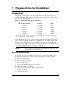
1 Prepare Drive for Installation Introduction This chapter describes the tools, setup information and the steps necessary to install a SCSI hard disk drive into an HP NetServer. The drives documented in this guide are listed in Table 1-1. Table 1-1. Hard Disk Drive Product Numbers HP Product Number Capacity RPM P1213A 9.10 GB 7200 P1214A 9.10 GB 10000 P1215A 18.2 GB 7200 P1167A 18.2 GB 10000 P1169A 36.
Chapter 1 CAUTION Prepare Drive for Installation In a few cases, drives with the same product number can be of different types and require different jumper settings. If your drive does not match the type in the figure, check the other figures for the matching type. Step 1: Prepare for Installation Gather the tools and the setup information you need to install the drive, before removing the drive from its packaging.
Chapter 1 Prepare Drive for Installation Unpack the Drive CAUTION Shock: Hard disk drives are very susceptible to mechanical shock and can be damaged by a drop as short as one-quarter of an inch (.64 cm). Take care when unpacking and handling the disk drive. If the drop would crack an egg, it will damage the drive. Static: Protect the hard disk drive from static electricity by leaving it in its antistatic bag until you are ready to install it.
Chapter 1 Prepare Drive for Installation Type 1 P1213A P1214A P1215A P1167A P1169A 9.10 GB Model 9.10 GB Model 18.2 GB Model 18.2 GB Model 36.4 GB Model Type 2 P1213A P1214A P1215A P1167A P1169A 9.10 GB Model 9.10 GB Model 18.2 GB Model 18.2 GB Model 36.4 GB Model Type 3 P1213A P1214A P1215A P1167A P1169A 9.10 GB Model 9.10 GB Model 18.2 GB Model 18.2 GB Model 36.4 GB Model Figure 1-1.
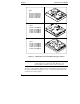
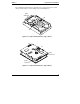
Chapter 1 Prepare Drive for Installation The "Disk Drive Characteristics" appendix shows a legend of the drive control settings and the jumper control settings for the individual drives. SCSI Connector J6 J4 Figure 1-2. Component Identification, Type 1 Drives J6 1 J2 15 1 SCSI Connector Power Connector Figure 1-3.
Chapter 1 Prepare Drive for Installation CN2 N2 Power Connector SCSI Connector Figure 1-4. Component Identification, Type 3 Drives Step 3: Set the SCSI Address The SCSI address is set using jumpers located on the drive. SCSI addresses range from 0 to 15. • Each drive is preset to SCSI address 3. • Address 7 is reserved for communications with the SCSI host bus adapter. Set the drive to the lowest available SCSI address. Address 0 should be used for the first drive in the system.
Chapter 1 Prepare Drive for Installation R RL A AAA E E E 3 210 S SD J4 1 7 J4 7 1 J6 G A RRR R E EEPEDM S SSDSSE J6 68-Pin SCSI Connector G A J4 1 SCSI 0 SCSI 3 SCSI 4 SCSI 5 SCSI 6 SCSI 7 SCSI 8 SCSI 9 SCSI 10 SCSI 11 SCSI 12 SCSI 13 SCSI 14 SCSI 15 Figure 1-5.
Chapter 1 Prepare Drive for Installation J2 J6 RR SDMWPEET ES EP DSSP 15 1 1 J2 15 1 68-Pin SCSI Connector J6 1 SCSI 0 SCSI 1 SCSI 2 SCSI 3 SCSI 4 SCSI 5 SCSI 6 SCSI 7 SCSI 8 SCSI 9 SCSI 10 SCSI 11 SCSI 12 SCSI 13 SCSI 14 SCSI 15 Figure 1-6.
Chapter 1 Prepare Drive for Installation RLRR N R E E E ES / D EAAAA CN2 S D S S E WS S 3 2 1 0 1 1 CN2 N2 68-Pin SCSI Connector CN2 1 SCSI 0 SCSI 1 SCSI 2 SCSI 3 SCSI 4 SCSI 5 SCSI 6 SCSI 7 SCSI 8 SCSI 9 SCSI 10 SCSI 11 SCSI 12 SCSI 13 SCSI 14 SCSI 15 Figure 1-7.
Chapter 1 Prepare Drive for Installation Step 4: Connect SCSI Cable Adapter (if required) The SCSI cable adapter, HP part number 5182-4551 (see Figure 1-8), allows you to connect an Ultra3 SCSI drive to a narrow SCSI cable and narrow SCSI controller (9.10 GB only). If you are not connecting your drive to a narrow cable, continue with Step 5. Ultra3 SCSI Connector Narrow SCSI Connector Figure 1-8.
2 Mount the Drive in the NetServer L Series This chapter describes the installation of a drive in the NetServer L Series. Step 1: Mount the Drive in the System Use the tray with the drive activity light for mounting a drive in the front of a NetServer. The drives are shipped already mounted on this tray. To purchase the tray separately, order Product Number D2198B (multipack). Figure 2-1.
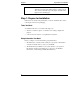
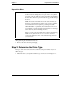
Chapter 2 Mount the Drive in the NetServer L Series Step 2: Connect the Drive Activity Light The mounting tray (D2198B) has a drive activity light on the front-panel. The drive activity light flashes during data access and the drive power-on self-test. Connect the drive activity light for your drive as shown in Figures 2-2, 2-3, and 2-4. 1 7 L E D 7 J4 J4 1 +5V Red Cable Black Cable Drive Activity LED Figure 2-2.
Chapter 2 Mount the Drive in the NetServer L Series L E D J6 1 J2 +5V Red Cable Black Cable RR SDMWPEET ES EP DSSP 15 1 1 Drive Activity LED J2 15 1 Figure 2-3. Activity Light Connection, Type 2 Drives RLRR N R E E E ES / D EAAAA CN2 S D S S E WS S 3 2 1 0 1 +5V Red Cable Black Cable Drive Activity LED 1 CN2 N2 Figure 2-4.
Chapter 2 Mount the Drive in the NetServer L Series Step 3: Connect the Drive In this step, you install the drive in the system, and connect the SCSI data cable and the drive power cable. The SCSI cable is connected to the SCSI connector on the system board or to a SCSI host bus adapter board. In order to run in LVD mode, the term "LVD" must also appear on the termination module. (Not all NetServer L Series have LVD 68-pin cables.
Chapter 2 Mount the Drive in the NetServer L Series • Record information about the new hard disk setup, including: model number, capacity, and SCSI address. • Reassemble your HP NetServer. • Connect all the cables and power cords. • Power up your HP NetServer. NOTE If a drive recognition error displays during system startup, press Ctrl+Alt+Del to restart the system. Do not power cycle the system because the drive recognition error will likely repeat.
3 Mount the Drive in the NetServer E 45 or E 50 This chapter provides instructions for installing a hard disk drive in the HP NetServer E 45 or E 50. Consider the following when installing a drive in an HP NetServer E Series system. • The HP NetServer E 45 supports up to four 9-GB Ultra3 SCSI 7200-RPM drives. • Only drive type P1213A is supported in the HP NetServer E 45. • All Ultra3 SCSI drives are not supported in the HP NetServer E 40 or the HP NetServer E 30.
Chapter 3 Mount the Drive in the NetServer E 45 or E 50 Power Switch System Board IDE1 Key IDE2 Available Connector Flexible Disk Controller Engaged Connector F5 D5 C33 SCSI Card PCI 1 C33 50-pin SCSI Cable D5 IDE CD-ROM Cable Flexible Disk Shelf 1 CD-ROM Shelf 2 * Shelf 5 Shelf 6 Shelf 3 F5 Flexible Disk Cable * Built-in SCSI Terminator Shelf 4 For cabling options and connector locations, see the Technical Reference Label inside your HP NetServer chassis. Figure 3-1.
Chapter 3 Mount the Drive in the NetServer E 45 or E 50 Step 2: Mount the Drive in the System To prepare to install the drive: • Turn off your system and the display. • Disconnect the power cords. • Detach any external cables. • Remove the cover from the HP NetServer. • Remove any hardware necessary to reach the cables or insert the drive. Consult Information Assistant on the HP NetServer Navigator CD-ROM for your system for specific instructions for removing components.
Chapter 3 Mount the Drive in the NetServer E 45 or E 50 • Align the four screw holes in the bottom of the NetServer E 45 tray with the four screw holes in the bottom of the drive. • Loosely install all of the screws, then tighten the screws to no more than eight inch-pounds (0.9 Newton-meter). • Place the tray in the shelf opening and slide the tray into the shelf. • Align the screw holes at the front of the tray with the holes in the front of the chassis.
Chapter 3 Mount the Drive in the NetServer E 45 or E 50 • Record information about the new hard disk setup, including: model number, capacity, and SCSI. • Reassemble the HP NetServer. • Connect all the cables and power cords. • Turn on power to the HP NetServer. Step 4: Configure the Drive Configure the SCSI controller for the drive using the SCSI SelectTM utility. • If the SCSI controller is not yet configured, run the SCSI Select utility, included with your system.
A Jumper Settings The hard disk drives are shipped without SCSI terminators. These drives are ready to use on a SCSI cable with a built-in active terminator. Each hard disk drive is configured at the factory for optimum performance on most systems. With the possible exception of setting the SCSI address, you should not change default settings. Changing the disk drive configuration can cause unexpected or undesirable results. Jumper Legend Table A-1 shows the jumper descriptions for all drives.
Appendix A ID Jumper Settings Description Off* PD Spindle starts immediately after power up. If Delay Spin-Up is on, it overrides this setting. Parity Disable On Parity checking and parity error reporting by the drive is disabled. Off* Parity checking and parity error reporting by the drive is enabled. The drive checks for parity and reports the results of parity checking to the host system. RES Reserved This pin set is not used and must remain as set at the factory.
B Disk Drive Characteristics The proper settings for the following items depend on the operating system (NetWare, MS-DOS, OS/2, Windows NT, UNIX, Banyan Vines, Windows 2000, or Linux) and corresponding version number: • Extended Translation setting for the controller • Partitions, logical drives or divisions for the hot swap hard disk drive For non-UNIX systems, partition and logical hot swap hard disk drive sizes also depend on: • Partition type (Bootable or Non-bootable) • File system (FAT, HPFS or NTFS
C Returning HP Hard Disk Drives When returning a drive for service, repair, or replacement, use the packaging supplied with the exchange drive. Foam Antistatic Bag Hard Disk Drive Figure C-1.
D Warranty and Support The hardware warranty below applies to components purchased as accessories. If your component was factory installed as part of an HP NetServer model, refer to the warranty statement provided with your system documentation. Hardware Warranty This HP NetServer accessory is covered by a limited hardware warranty for a period of one year from receipt by the original end-user purchaser.
E Regulatory Information DECLARATION OF CONFORMITY according to ISO/IEC Guide 22 and EN 45014 Manufacturer’s Name: Address: Hewlett-Packard Company 10955 Tantau Avenue Cupertino, CA 95014 USA declares, that the product Product Name: 9-GB, 18-GB, and 36-GB Ultra3 SCSI Disk Drives Model Number(s): HP P1213A, HP P1214A, HP P1215A, HP P1167A, and HP P1169A Product Options: N/A conforms to the following Product Specifications: Safety: EMC: IEC 950:1991 + A1, A2 / EN 60950 (1992) + A1, A2 CISPR 22:1985
Index A active termination, 14, 20 adapter, SCSI cable, 10 D delay spin-up, 23 Delay Spin-Up, 23 disk drive configuration, 23 drive format, 15, 21 logical partition, 15, 21 NetServer tray, 11 product number, 1 drive activity light, 12, 23 D4910A, 12 D4911A, 12, 13 drive style D4910A, 6 D4911A, 5, 6 F file system initialization, 15, 21 front mounting tray, 12 H hardware warranty, 29 HP Information Assistant CD-ROM, 2 HP NetServer Road Map, 2 I installation general procedure, 1 NetServer E 45, 17 internal pow
Index SCSI host bus adapter, 6, 14, 20 SCSI Select utility, 15, 21 SCSI terminators, 23 setup information, 2 shock, 3 start unit command, 24 static electricity, 3 support, 29 system board, 14, 20 system boot, 15, 21 T tools, 2 U Ultra Wide SCSI connector, 10 W write protect, 24 34