HP NetServer E 800 Installation Guide HP Part Number D9394-90000 Printed June 2000
Notice The information contained in this document is subject to change without notice. Hewlett-Packard makes no warranty of any kind with regard to this material, including, but not limited to, the implied warranties of merchantability and fitness for a particular purpose. Hewlett-Packard shall not be liable for errors contained herein or for incidental or consequential damages in connection with the furnishing, performance, or use of this material.
Contents Setting Up the HP NetServer E 800................................................................. 1 Introduction ................................................................................................... 1 Step 1: Attaching all the Cables................................................................. 2 Step 2: Opening the HP NetServer............................................................ 3 Step 3: Installing Memory ..................................................................
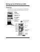
Setting Up the HP NetServer E 800 Introduction This installation guide is a quick reference for HP NetServer E 800 installation. Skip any steps that do not apply to your installation. Refer to the figures below for connection and operating information. For more information, refer to the HP NetServer E 800 User Guide.
Setting Up the HP NetServer E 800 Step 1: Attaching all the Cables If you are not installing any accessories, attach all available cables to the respective connectors, then go to "Step 7: Configuring the HP NetServer." NOTE The two USB connectors are reserved for printers, scanners, and external modems. The NetServer does not support USB connections for the keyboard and mouse.
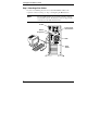
Setting Up the HP NetServer E 800 Step 2: Opening the HP NetServer Tools Required: • ¼ inch flat-blade screwdriver • Torx T-15 driver WARNING Before removing the cover, always disconnect the power cord and remove the telephone cable. Disconnect the power cord to avoid exposure to high energy levels that may cause burns when parts are short-circuited by metal objects such as tools or jewelry. Disconnect telephone cables to avoid exposure to shock hazard from telephone ringing voltages.
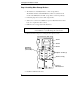
Setting Up the HP NetServer E 800 Front of Chassis Cover Cover Bottom of Chassis Latch Opening Air Duct Latch 4
Setting Up the HP NetServer E 800 Step 3: Installing Memory • Use only HP DIMMs, which are 3.3V, 168-pin, PC133 (133 MHz), buffered SDRAM DIMMs in 128 MB, 256 MB, or 512 MB. • DIMMs may be installed in any slot, in any combination (sizes mixed), in any order, but HP recommends starting at slot 0 and filling the slots in order with the largest size first: 0, 1, 2, and 3. • Ensure both latches close on the DIMM when completely installed.
Setting Up the HP NetServer E 800 Step 4: Installing Mass Storage Devices • The NetServer is internally limited to 7 mass storage shelves. The flexible disk drive and CD-ROM drive, which are standard on all models of the HP NetServer E 800, occupy shelves 1 and 2 respectively. • If a backup tape drive is used, it will occupy shelf 3. • Shelves 4, 5, 6, and 7 are available for up to four SCSI hard drives and at least one is required for the boot drive. • IDE drives are not supported in this NetServer.
Setting Up the HP NetServer E 800 3. Connect the cables (data & power). 4. Replace the drive cage. Slots for Tabs Tabs(2) Captive Screws (3) First insert screws through round holes in back (one on each side). CAUTION All mounting screws used to thread into the hard disk drive must be #6-32 and not exceed ¼-inch in length. Longer screws may cause internal damage to the mass storage device. Damage caused by incorrect mounting screws is not covered by the HP warranty.
Setting Up the HP NetServer E 800 5. If necessary, install the internal accessory SCSI cable into SCSI channel B and connect to the SCSI drives or optional backup tape drive. Use HP NetServer E 800 External/Internal SCSI Cable Kit, part number P1773A. Terminator SCSI Connectors (2) SCSI B Connector NOTE 8 The slower speed of the tape drive may slow disk access time for the Ultra-2 SCSI drives.
Setting Up the HP NetServer E 800 6. If necessary, install the external/internal SCSI cable into SCSI channel B and connect to the knock-out in the rear of the chassis. Use HP NetServer E 800 External/Internal SCSI Cable Kit, part number P1774A. WARNING Ensure you do not touch the sharp metal edges from the knock-out once you have removed it. The empty knock-out leaves sharp metal on the edges.
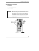
Setting Up the HP NetServer E 800 Step 5: Installing Adapter Boards • The NetServer E 800 has two PCI (Primary and Secondary) busses and both are pear-to-pear, which provides approximately equal performance, except when using the two 64-bit slots versus the 32-bit slots. PCI Slots PCI Bus Slots 1 through 4 Primary PCI Bus Slots 5 through 7 Secondary PCI Bus NOTE Some full-length PCI boards may need a plastic "handle" (board extension) on one end to stabilize the board in the NetServer.
Setting Up the HP NetServer E 800 System Board (Top View) 32-bit PCI Slot 1 PCI Slot 2 WakeOnLAN 32-bit FullLength 64-bit PCI Slot 5 64-bit PCI Slot 6 32-bit PCI Slot 7 11
Setting Up the HP NetServer E 800 Slot Cover Chassis CrossSection View 12
Setting Up the HP NetServer E 800 13
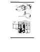
Setting Up the HP NetServer E 800 Step 6: Installing a Second Processor • Both processors must have the same clock speed and cache size. • Use only processor upgrade kits with the same HP product number. This ensures the product numbers are compatible and the processor type, clock speed, and cache size are the same. CAUTION Do not open the new processor’s protective bag or remove it from the bag until you are ready to install it.
Setting Up the HP NetServer E 800 1. Open the ZIF (Zero Insertion Force) lever on the processor socket. The ZIF lever must open completely to a full 90° before removing the terminator from the socket. 2. Remove the terminator from the processor socket. Terminator Processor Socket ZIF Lever NOTE Retain the terminator for future use. The NetServer will not operate properly if using only one processor with no terminator installed.
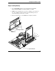
Setting Up the HP NetServer E 800 3. Insert the processor into socket, matching pin-1 to marker. Pin-1 Marker 4. Close the ZIF lever with a click. The ZIF lever should click when closed.
Setting Up the HP NetServer E 800 5. Place the Heatsink-Fan on top of processor and follow the steps A-C in the figure below. Hook Latch (hidden) B. Rotate back and hook the Thumb Latch. A. Rotate and hook. Thumb Latch Tab Tab C. Ensure this ridge rests between the CPU and the edge of the processor socket. Processor Socket Base CAUTION Failure to properly seat the heatsink-fan assembly on the processor will cause it to overheat and shutdown the NetServer within 20 seconds of powering on.
Setting Up the HP NetServer E 800 6. Connect the fan connector to the respective connector on the system board. Processor 1 (CPU 1) CPU 1 Fan System Fan Power Connector Processor 2 (CPU 2) CPU 2 Fan CAUTION 18 Failure to connect the fan connector will cause the processor to overheat and the NetServer will shut down without any messages being displayed. If the processor is allowed to overheat, damage may occur.
Setting Up the HP NetServer E 800 Step 7: Configuring the HP NetServer 1. Power on the HP NetServer and the monitor: ◊ Insert the HP NetServer Navigator CD-ROM in the CD-ROM drive. ◊ The server should boot from the HP NetServer Navigator CD on its own, if not, turn the power off, wait 10 seconds and turn the power back on again. ◊ If the system fails to boot, follow the instructions on the screen. ◊ Press [F2] to enter Setup, or ◊ Press [F4] to accept automatic configuration update 2.
Setting Up the HP NetServer E 800 SCSI controller board from a third-party). You will need to use the NOS vendor’s installation process. Be sure to first view and print the HP-customized NOS installation instructions and create the driver disk(s) for the NOS you are installing before leaving Navigator and installing your NOS. 3. Install or Configure Tape Backup Software: ◊ If your NetServer includes a preinstalled tape backup device, install and/or configure the tape backup software now.