HP NetServer E 60 Installation Guide Online Version: B Updated May 1999
Notice The information contained in this document is subject to change without notice. Hewlett-Packard makes no warranty of any kind with regard to this material, including, but not limited to, the implied warranties of merchantability and fitness for a particular purpose. Hewlett-Packard shall not be liable for errors contained herein or for incidental or consequential damages in connection with the furnishing, performance, or use of this material.
Contents 1 Setting Up the HP NetServer E 60 ...............................................................1 Setup Steps ...................................................................................................1 Preparations...............................................................................................1 Installation Options.....................................................................................2 Configuring the System....................................................
Contents 6 Installing Additional Boards......................................................................35 Introduction ..................................................................................................35 Tools Required.............................................................................................35 Installation Basics ........................................................................................35 Interrupt Sharing ..............................................
Contents 10 Information Assistant................................................................................59 Overview......................................................................................................59 Using Information Assistant..........................................................................59 Getting Help.............................................................................................59 Finding Information ..................................................
Contents Battery Problems..........................................................................................80 To Install a Replacement Battery .............................................................80 Problems Running the Setup Program .........................................................81 A Specifications ............................................................................................83 Environment..............................................................................
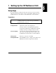
1 Setting Up the HP NetServer E 60 Setup Steps It is important that you follow the setup steps in the exact order shown below. Skip any steps that do not apply to you. To provide further details, these steps include references to other sections of this manual and to other documents. Preparations CAUTION The HP NetServer E 60 weighs approximately 31 pounds, excluding a keyboard or monitor. Use appropriate lifting precautions when you move it. Verify Contents Unpack the contents of the shipping box.
Chapter 1 Setting Up the HP NetServer E 60 Support Documentation HP NetServer E 60 Installation Guide This document describes installation, hardware upgrades, configuration, and troubleshooting of your HP NetServer E 60. HP NetServer Online Documentation CD-ROM A hypertext online documentation system that contains the entire set of documentation for the E 60. See Chapter 10 for details on using this. Technical Reference Card A card that summarizes key technical data on the E 60.
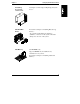
Chapter 1 Setting Up the HP NetServer E 60 If Installing Accessories, remove Cover See Chapter 3, "Removing and Replacing the System Cover." Add Hard Disk Drives For details see Chapter 4, "Installing Mass Storage Devices." An optional external SCSI port cable kit is available to extend one of the system's embedded SCSI ports to the rear of the system. Add Memory Use HP DIMMs only. Supported DIMMs may be installed in any combination, in any sockets.
Chapter 1 Add PCI Boards Setting Up the HP NetServer E 60 Note that slot assignments of disk drive controller cards affects boot order. For details see Chapter 6, "Installing Additional Boards." Add a Processor The HP NetServer E 60 supports either Pentium II or Pentium III processors. Do not mix Pentium II and Pentium III processors in the system. Do not mix processors with different clock speeds in the system. For details see Chapter 7, "Installing a Second Processor.
Chapter 1 Setting Up the HP NetServer E 60 Configuring the System 1) Connect Peripherals For details on rear panel interface connectors, see Chapter 2. For details on connecting the keyboard, mouse, monitor, and UPS, see Chapter 8. 2) Boot the HP NetServer Navigator CD-ROM Turn on the monitor. Press the power-on button on the HP NetServer, and press the eject button on the CD-ROM drive. Place the HP NetServer Navigator CD-ROM in the drive, and close the drive. Press the Reset button.
Chapter 1 6) Select the NOS Installation Mode Setting Up the HP NetServer E 60 Automated NOS install: If you select certain versions of Novell NetWare or Microsoft Windows NT Server, you will be asked, "Would you like to use HP's automated mode of NOS installation?" Choose automated NOS installation mode for a first-time installation of Novell NetWare or Microsoft Windows NT Server on a factory configured HP NetServer E 60.
Chapter 1 Setting Up the HP NetServer E 60 10) Run DiagTools (Optional) To verify that the HP NetServer hardware is fully functional, create a DiagTools diskette to run DiagTools from after configuration. Select NetServer Utilities from the HP Navigator main menu, and then select DiagTools from the NetServer utilities menu. 11) HP NetServer Management Refer to the HP NetServer Management Reference Guide to install HP TopTools, set up the Remote Console feature and other server management options.
2 Controls, Indicators, and Ports Front Panel Before installation, familiarize yourself with the HP NetServer E 60's switches and LED (Light Emitting Diode) indicators. The connections, switches, indicators, ports and the user-serviceable internal components of the NetServer E 60 are shown in Figure 2-1. Figure 2-1.
Chapter 2 Controls, Indicators, and Ports Table 2-1 shows the Control panel switches and the associated indicator definitions. Table 2-1. Control Panel Switch and Indicators Control / Indicator Power On/Off/Sleep Switch Description The power button acts as both a button for transitioning the system between the on and sleep states, and for transitioning the system between the off and on states. With the system on, pressing this button will set the system into the sleep state.
Chapter 2 Controls, Indicators, and Ports Rear View The ports and connectors in the rear are listed below, and shown in Figure 2-2. • The system includes a LAN port based on the Intel 82559 10/100 BaseT Fast Ethernet PCI embedded controller. It has an RJ-45 LAN connector and two LEDs to indicate LAN speed and valid connection. • The Serial Port A is a standard serial port. • The Serial Port B is a standard serial port.
Chapter 2 Controls, Indicators, and Ports Power Keyboard Mouse Key Lock Serial Port A Parallel Port Serial Port B LAN RJ45 External SCSI Port Knock-out Video SVGA Figure 2-2.
Chapter 2 Controls, Indicators, and Ports Table 2-2 shows the LAN LED indicators. Table 2-2. LAN Port (RJ45) LED Indicator Definitions Definition Indicator This green LED is the activity/link indicator. When steady on, this LED indicates a valid LAN link. This LED will also flash when there is LAN activity. Link LED LAN Speed Indicator This yellow LED is the LAN speed indicator. The LED remains off to indicate 10 Mbps, and steady on to indicate 100Mbps LAN speed.
Chapter 2 Controls, Indicators, and Ports 2. Press the power switch on the HP NetServer's control panel when prompted by the operating system. Normally this is the complete procedure. NOTE 14 The power supply will continue to provide standby current to the NetServer until the power cable is disconnected from the rear panel.
3 Removing and Replacing the System Cover Removing and Replacing the Cover WARNING Before removing the cover, always disconnect the power cord and unplug telephone cables. Disconnect the power cord to avoid exposure to high energy levels that may cause burns when parts are short-circuited by metal objects such as tools or jewelry. Disconnect telephone cables to avoid exposure to shock hazard from telephone ringing voltages.
Chapter 3 Removing and Replacing the System Cover Key Lock Screws Screws Figure 3-1. Screws and Lock Holding on Cover 4. Remove the NetServer cover. Place your hands near the bottom front of the cover, one along each side. Pull the cover slightly back to release it and then lift up and off the chassis (see Figure 3-2). Figure 3-2.
Chapter 3 Removing and Replacing the System Cover Replacing the Cover To replace the cover, follow these steps: 1. If necessary, return the air duct to its closed position. 2. Place one hand on either side of the cover and press inward lightly while lowering the cover onto the chassis. The cover has flanges that rest on the rails inside the chassis (see Figure 3-3). Front of Chassis Bottom of Chassis Figure 3-3. Replacing the Cover 3. Push the cover forward until it is seated in place. 4.
Chapter 3 Removing and Replacing the System Cover Adjusting the System Feet When adding internal accessories to the system, turn the feet inward so that the system will lay flat on its side on the floor. Figure 3-4.
4 Installing Mass Storage Devices Introduction The HP NetServer E 60 comes standard with an IDE CD-ROM and a floppy disk drive (some models also include a SCSI hard disk drive and a tape backup drive). The internal mass storage cage can hold, and cabling is provided for, up to four Ultra Wide SCSI hard disk drive devices. The SCSI cable has five 68-pin, high-density connectors for the available hard disk drive shelves.
Chapter 4 Installing Mass Storage Devices For information about booting off of a hard disk connected to an accessory board, see "Installing a Disk Array Controller Board and Altering the Boot Priority" in Chapter 6. NOTE The boot order can be changed using the system's BIOS Setup utility (press [F2] during the boot process).
Chapter 4 Installing Mass Storage Devices Embedded SCSI Controller Configuration Typically, no configuration of the embedded SCSI controller is required. You do have the option of reassigning the designation of channel A and B. In order to verify or modify SCSI host adapter settings, or to low-level format SCSI disks or verify SCSI media, run the SCSI Select Utility. See Chapter 11, "Using the BIOS Setup and SCSI Select Utilities," for further information.
Chapter 4 Installing Mass Storage Devices 4. Lay the server on its side (components showing). Unsnap the air duct and move it out of the way (see Figure 4-1). Figure 4-1. Moving the Air Duct 5. Loosen three captive screws on the mass storage cage (see Figure 4-2). 6. Unplug the power and SCSI cables to any hard disk drives already in the cage. CAUTION 22 Install and remove connectors carefully, and avoid displacing any the pins.
Chapter 4 Installing Mass Storage Devices Top Hard Disk Drive Cage Screws Front Figure 4-2. Captive Screws Holding the Hard Disk Drive Cage 7. Remove the cage (see Figure 4-3). CAUTION All mounting screws that thread into the hard disk drive must be #6-32 and not exceed ¼-inch in length. Longer screws may cause internal damage to the mass storage device. Damage caused by incorrect mounting screws is not covered by the HP warranty. 8.
Chapter 4 Installing Mass Storage Devices Figure 4-3. Adding a Hard Disk Drive 9. Install the screws that secure the drive (or the shelf or the brackets) to the mass storage cage. First, attach one of the screws through the round screw hole at the rear of the cage, then through the elongated hole at the front of the cage. Repeat on the other side of the cage (see Figure 4-4).
Chapter 4 Installing Mass Storage Devices 3rd 2nd 4th 1st HDD 1 HDD 2 HDD 3 Tabs HDD 4 Figure 4-4. Hard Disk Drive Cage Screw Holes 10. Reinstall the mass storage cage. Make sure the tabs at the front on the cage slide into the slots provided for them (see Figure 4-3). 11. Connect the SCSI cable to the disk drive. There are five connectors on the SCSI cable. The first four are intended for the four hard disk drive positions in the hard disk drive cage.
Chapter 4 Installing Mass Storage Devices Installing the Optional HP NetServer E 60 Duplexing Cable Kit The E 60 can be configured to allow two-channel duplexing using the embedded SCSI controller. This means that if you intend to mirror drives you have the additional safety option of having your mirrored drives on two different SCSI channels in case one channel goes down.
Chapter 4 Installing Mass Storage Devices 1. To install the external cable, connect one end to the free SCSI connector on the System board (refer to the Technical Reference Card on the chassis for location). 2. Using a flat blade screwdriver, pop out the external SCSI knock-out at the rear of the system (see Figure 4-7 for location). 3.
Chapter 4 Installing Mass Storage Devices 4. Install the external connector end of the cable to the rear where the knockout was removed and insert the two threaded studs from the outside (see Figure 4-7). Figure 4-7.
5 Installing Additional Memory Introduction The NetServer E 60's main memory is implemented with 3.3V, 100 MHz, unbuffered SDRAM DIMMs (Dual In-Line Memory Modules). The NetServer E 60 ships with at least 64 MB of main memory and supports up to 1 GB. Memory is available in the following DIMM capacities: 64, 128, and 256 MB. Tools Required Use an anti-static service kit (3M 8501/8502/8503 or equivalent). This kit includes a static-dissipating work surface, a chassis clip lead, and a wrist strap.
Chapter 5 Installing Additional Memory 4. Lay the server on its side (components showing). 5. Unsnap the air duct and move it out of the way (refer to Figure 4-1). CAUTION The memory modules are sensitive to static electricity and can be easily damaged by improper handling. Do the following when handling the accessory kit: Leave the memory module in the anti-static container until you are ready to install it. Use an anti-static wrist strap and a grounding mat.
Chapter 5 Installing Additional Memory 7. Install the DIMMs (see Figures 5-2 and 5-3): a. Remove a DIMM from its container, handling the module by its edges. Lay it on an anti-static surface. b. Choose a socket into which you want to install a DIMM. DIMMs may be installed in any combination, in any socket. CAUTION Use only HP DIMMs. c. Spread the two retaining clips on the socket outward. d. Align the notches on the DIMM with the keys on the socket (see Figure 5-2).
Chapter 5 Installing Additional Memory Figure 5-3. DIMM Insertion 8. Repeat to install all of the DIMMs for your memory configuration. NOTE Most DIMMs are dimensionally identical, so, if you have three or more DIMMs installed, you may check that they are all seated by sliding a straight edge (a pen, for example) across their top edges and checking that it remains in continuous contact with all of the DIMMs.
Chapter 5 3. 4. 5. 6. 7. Installing Additional Memory Remove the top cover from the NetServer. See Chapter 3 for details. Open the retaining clips. Lift the DIMM completely away from the socket. Place the DIMM in its anti-static container. Repeat steps 4-6 for as many DIMMs as you need to remove.
6 Installing Additional Boards Introduction The HP NetServer E 60 includes six PCI slots and one ISA slot that is shared with PCI slot 6. PCI slots 3-6 have a slot guide for full-sized boards (as shown in Figure 6-1). This chapter tells how to use the six available expansion slots. For the latest information on accessory cards for the E 60, including slot recommendations, see the Readme file and Configuration Advisor on your HP NetServer Navigator CD-ROM (for instructions, see Chapter 9).
Chapter 6 Installing Additional Boards caused the interrupt before it responds. For example, if you have drives connected to the embedded SCSI controller, use the other PCI slots before using slot 3. IRQs are shared in the HP NetServer E 60 system as shown below. If you are installing a PCI board that does not support interrupt sharing (refer to the accessory board documentation), make sure that the shared slot is empty or has no embedded device assigned to it.
Chapter 6 Installing Additional Boards PCI Slot Initialization Order During system boot, the PCI slots are initialized in the following order: PCI slot 2 PCI slot 1 PCI slot 6 PCI slot 3 PCI slot 4 PCI slot 5 Installing a Disk Array Controller Board and Altering the Boot Priority Adding a disk array controller board provides additional fault tolerance to your internal or external mass storage devices.
Chapter 6 Installing Additional Boards 4. Lay the server on its side (components showing). 5. Read the documentation that is included with the accessory card. Note any special instructions. NOTE Adding a PCI-to-PCI bridge card to the HP NetServer may alter the server's boot order. This boot order can be changed using the SETUP utility (press [F2] during the boot process). Refer to Chapter 4, "Installing Mass Storage Devices," and see the subsection, "Boot Priority." 6.
Chapter 6 Installing Additional Boards 7. Use the T15 driver or flat blade screw driver to remove the PCI slot cover for each slot to be used, and store it for future use (see Figure 6-2). Figure 6-2. Removing the Accessory Slot Cover 8. Slide the accessory board into the slot (see Figure 6-3).
Chapter 6 Installing Additional Boards Figure 6-3. Inserting an Accessory Board 9. Secure the accessory board using the screw you previously removed with the slot cover. Use the T15 driver or flat blade screw driver. Once the accessory board is installed, you may need to install software drivers. The drivers for the new board are either part of your existing system software or included on a floppy diskette that accompanies the accessory.
7 Installing a Second Processor Introduction The NetServer E 60 supports up to two processor modules. Processor modules are available at different clock speeds. The HP NetServer E 60 supports either Pentium II or Pentium III processors. Do not mix Pentium II and Pentium III processors in the system. Do not mix processors with different clock speeds in the system (example: 400MHz and 450MHz processors). Note that compatible processors are not necessarily identical in appearance.
Chapter 7 CAUTION Installing a Second Processor Wear a wrist strap and use a static-dissipating work surface connected to the chassis when handling components. Ensure that the metal of the wrist strap contacts your skin. Determine Where to Place the Processor Module 1. Locate the processor cage on the system board (see Figure 7-3). 2. Check the processor clock switch settings and determine the clock speed of the processor module already on the system board (see Figure 7-1).
Chapter 7 Installing a Second Processor Leave the processor module in the anti-static container until you are ready to install it. Use an anti-static wrist strap and a grounding mat. Before you remove a processor module from the anti-static container, touch a grounded, unpainted metal surface on the HP NetServer E 60 to discharge static electricity. 1. Remove the terminating resistor module from the secondary processor slot as shown in the following illustration.
Chapter 7 Installing a Second Processor Figure 7-3. Installing the Processor Module on the System Board 4. Rotate the plastic securing clips into position over the processor. These clips will only lay down flat against the top of the processor when the processor is fully seated. Upgrading the Firmware If your processor included a new HP NetServer Navigator CD-ROM, insert the CD into the HP NetServer E 60 CD-ROM drive and power on the system. Follow instructions to ensure that the BIOS is up-to-date.
Chapter 7 Installing a Second Processor Removing a Processor Module Use the same procedure as above, and simply remove rather than add the processor module. BE SURE to replace the terminating resistor module.
8 Connecting the Monitor, Keyboard, Mouse, and UPS Connect the monitor, keyboard, and mouse cables and the AC power cord to the appropriate connectors on the rear of the chassis. Use the power cord strain relief clamp to secure the power cord. When connecting the HP NetServer E 60 to peripherals, use the cable ties and labels that come with the product (see Figure 8-1).
9 Configuring the Server Using the HP NetServer Navigator CD-ROM The HP NetServer Navigator CD-ROM is shipped with your NetServer. You will use this CD-ROM to configure your NetServer. Contents of the HP NetServer Navigator CD-ROM The Main Menu of HP Navigator directs you to modules where you can perform configuration tasks or access online system documentation.
Chapter 9 Configuring the NetServer Using the HP NetServer Navigator CD-ROM Readme File This file includes the most recent information that was not available at the time that the installation documentation was printed. It is important to check this file before proceeding with the installation. Viewing the Readme File 1. Press the power-on button. Press the CD-ROM drive eject button. Place the HP NetServer Navigator CD-ROM in the drive, and press the eject button again to close the drive.
Chapter 9 Configuring the NetServer Using the HP NetServer Navigator CD-ROM Run Configuration Assistant and Installation Assistant Insert the HP NetServer Navigator CD-ROM into the CD-ROM drive. Turn the power off, wait 10 seconds, and turn the power on again. If the system fails to start, follow the instructions on the screen. 1. When HP NetServer Navigator starts, you may need to set the language, time, and date. Follow the onscreen instructions.
Chapter 9 Configuring the NetServer Using the HP NetServer Navigator CD-ROM to Windows NT systems. The Local TopTools for Servers program is a stand-alone support tool accessed directly from the NetServer. It gives you information to help you manage the NetServer. ◊ Select No for manual NOS installation.
Chapter 9 Configuring the NetServer Using the HP NetServer Navigator CD-ROM the configuration of the boards by selecting Execute on the Execute Board Utilities screen.
Chapter 9 Configuring the NetServer Using the HP NetServer Navigator CD-ROM ◊ Execute Board Utilities: When HP Navigator finds installed boards for which there are additional configuration utilities on the CD-ROM, this option becomes available to complete the configuration of the boards. Select Execute on the Execute Board Utilities screen. ◊ Install NOS (in automated NOS installation mode), or Create Drivers Diskette(s) (in manual NOS installation mode).
Chapter 9 Configuring the NetServer Using the HP NetServer Navigator CD-ROM If not, on the Show NOS Installation Instructions screen, select Save to Disk to copy the Network Operating System Installation Instructions to disk. Then print them out from the disk. Read the instructions first, and then follow them to manually install the NOS.
Chapter 9 Configuring the NetServer Using the HP NetServer Navigator CD-ROM proactive management of your HP NetServers. Processors, memory, storage, and NICs are a few examples of the components managed by TopTools.
Chapter 9 Configuring the NetServer Using the HP NetServer Navigator CD-ROM • You can also download the TopTools software and documentation from the NetServer Web Site at http://www.hp.com/go/netserver_mgmt pcANYWHERE32 pcANYWHERE32 is remote-control graphics-redirection software from Symantec Corporation included with your HP NetServer (on the HP NetServer Navigator CD-ROM) that allows you to take control of Microsoft Windows NT servers across the network or over a modem.
10 Information Assistant Overview The HP NetServer Online Documentation CD-ROM includes Information Assistant, which contains the entire set of documentation for your NetServer E 60.
Chapter 10 Information Assistant Finding Information Information Assistant provides many ways to navigate through its topics and locate information. For example: Map button. Displays a window with an outline of every module and topic in Information Assistant for the selected product. The Map enables you to view the contents of the Information Assistant in outline format, and then select a topic to view. Search button. Search performs full-text searches for topic text.
Chapter 10 Information Assistant Copying and Printing Information You can copy topic text in Information Assistant for use in other applications, such as word processors, by copying text onto the Windows Clipboard and pasting the text into any Windows application. To print topics in Information Assistant, use one of the print options on the File drop-down menu. You can choose to print the current topic or all of the topics in a product book.
Chapter 10 Information Assistant In Program Manager or the Programs group, the Setup utility creates a new program group called NetServer Information Assistant, with an icon for running the application.
11 Using the BIOS Setup and SCSI Select Utilities The HP NetServer E 60 BIOS Setup utility is used to configure the following system options: • User Preferences • Security • Configuration Using the BIOS Setup Utility Turn on the monitor and the NetServer, and start the Setup utility by pressing the [F2] key when Press to enter SETUP appears on the boot screen. The menu offers the choices listed above, and these choices are described here.
Chapter 11 Using the BIOS Setup and SCSI Select Utilities Configuration Use this menu option to configure I/O ports, I/O addressing, interrupts, PCI slot masters, IRQ interrupt locking, boot device ordering, embedded NIC enable/disable and Wake-on-LAN. • Integrated I/O Port. Configure ports for serial and parallel, assign base addresses and interrupts, pointing devices (mouse), and console redirection for remote control. • Flexible Disk Drive. Enable or disable the floppy disk drive controller.
Chapter 11 Using the BIOS Setup and SCSI Select Utilities Reserving Resources for ISA Non-Plug-and-Play Boards If you have installed an ISA non-Plug-and Play accessory board, you must reserve system resources for it. Turn on the monitor and the NetServer, and start the Setup utility by pressing the [F2] key when Press to enter SETUP appears on the boot screen. NOTE Pressing the [F2] key when prompted should start the Setup utility. For some ISA boards, the Setup utility will not start.
Chapter 11 Using the BIOS Setup and SCSI Select Utilities 6. Use the up and down arrow keys to highlight ISA non-Plug-and-Play Devices, and press Enter to select that submenu. 7. Use the up and down arrow keys to highlight Memory Resources, and press Enter to select that submenu. 8. Use the up and down arrow keys to highlight the memory block that corresponds to the memory range required for the ISA board you are installing, and press the + or - key on the keypad to reserve it.
Chapter 11 Using the BIOS Setup and SCSI Select Utilities 17. Use the up and down arrow keys to highlight the IRQ that corresponds to the IRQ required for the board you are installing, and press the + or - key on the keypad to reserve that IRQ. Reserve all IRQs needed for the board. 18. When all the necessary IRQs and other resources are reserved, press the [F10] function key to save and exit. 19.
Chapter 11 Using the BIOS Setup and SCSI Select Utilities 10. Then, after setting up your server and a remote PC console with modems, you install your terminal emulation software (pcANYWHERE32 included with the system) on the remote console to establish a connection. For indepth details on configuring and using the Remote Console feature, refer to the "Remote Console Feature" online documentation found under the Management button of Information Assistant.
Chapter 11 Using the BIOS Setup and SCSI Select Utilities • Run NetServer Diagnostics. This utility provides you with ways to test a NetServer's hardware components, including main circuit board function. • Remotely boot the server and view startup messages. • Set or reset system date, time, and keyboard language. In addition, your HP NetServer E 60 includes pcANYWHERE32 communications software (by Symantec Inc.
Chapter 11 Using the BIOS Setup and SCSI Select Utilities • Advanced Configuration Options Reset SCSI, display message, enables or disables SCSI BIOS and features. SCSI Disk Utilities Use this menu option to format and verify media. • Select device Select a device for low-level formatting or media verification. CAUTION 70 Low-level formatting of a disk drive will destroy all of its data.
12 Troubleshooting Troubleshooting Tools If you are having problems installing your HP NetServer, there are a number of different tools available for troubleshooting: • HP NetServer Information Assistant contains the following tools: ◊ Troubleshooting Information ◊ Parts Information ◊ List of Error Messages and Beep Error Messages • Navigator CD-ROM contains NetServer Utilities.
Chapter 12 Troubleshooting If the System Will Not Power On Follow these steps if the power/activity light does not light green after you press the power-on button: 1. Remove the AC power cord, wait 15 seconds, reconnect the power cord, and try again. 2. Check to ensure that all cables and power cords are firmly plugged into their proper receptacles. 3. If the server is plugged into a switched multiple-outlet box, make sure the switch on the outlet box is turned on. 4.
Chapter 12 WARNING Troubleshooting Before removing the cover, always unplug telephone cables and disconnect the power cord. Unplug telephone cables to avoid exposure to shock hazard from telephone ringing voltages. Disconnect the power cord to avoid exposure to high energy levels that may cause burns when parts are short-circuited by metal objects such as tools or jewelry. 2.
Chapter 12 Troubleshooting After Installing an Accessory 1. Turn off the monitor, the computer, and any external devices. 2. Unplug all cables from the power outlet. 3. Remove the cover. 4. Check the following: ◊ If you have installed an accessory board, check that the board is firmly seated in its slot and that any switches or jumpers on the accessory board are properly set. (Refer to the manuals that came with each board.) ◊ Check all internal cabling and connections.
Chapter 12 Troubleshooting Clearing the CMOS Configuration You may need to clear the CMOS configuration if the configuration has been corrupted by a program, or if incorrect settings made in the Setup program have made the display unreadable. To clear the configuration: 1. Turn off power to the NetServer and remove the cover and the cooling duct/cover. 2. Move switch 4 on the system board (labeled "Clear Configuration") to the ON position (see Figure 7-1). 3. Turn on power to the NetServer.
Chapter 12 Troubleshooting The following table describes power-on errors and the corrective action you may take to remedy the problem: Message Corrective Action Operating system not found Check whether the drive from which you are booting has the power and SCSI flat cables connected. Verify that the SCSI cable is securely plugged into the SCSI controller board. Check that the boot device is enabled in the Start-up center under the Security menu of the Setup program.
Chapter 12 Troubleshooting If a NetServer configuration error is reported during the startup routine, clear the CMOS memory as described under "Clearing the CMOS Configuration," and restart the NetServer. Hardware Problems This section describes what to do if you have problems with your monitor, mass storage devices, printer, accessory boards, keyboard, or mouse.
Chapter 12 Troubleshooting 4. If the screen goes blank after the NOS has booted, contact your HP support organization. The Keyboard or Mouse Does Not Work 1. Check that the keyboard and mouse are connected to the correct connectors. Refer to the I/O panel label on the rear panel of the NetServer. 2. Check that the mouse is correctly defined in the control options of your NOS. 3. Clean the mouse ball and rollers using a lint-free cloth. The CD-ROM Drive Does Not Work 1.
Chapter 12 Troubleshooting Password Problems This section describes some common password problems. Resetting Lost Passwords If you have forgotten the User or Administrator password, you can reset them. The User password can be reset if you know the Administrator password; the Administrator password can only be reset by a switch on the system board. User Password If you have forgotten the User password, but the Administrator password is set and known, perform the following steps: 1. Restart the NetServer.
Chapter 12 Troubleshooting 7. Replace the cooling duct/cover and the NetServer cover. 8. Turn on power to the NetServer and allow it to complete its startup routine. 9. If you wish to set passwords again, after the power-on system hardware test has completed, press [F2] to start the Setup program. 10. Set the new password(s). 11. Choose the Exit option and save the changes to save the new password(s).
Chapter 12 Troubleshooting Battery Figure 12-1. Battery on System Board 4. Insert the new battery with the positive sign (+) facing out, and ensure that it is seated completely. Make sure that the retaining clip is in place, and holds the battery firmly. 5. Replace the cooling duct/cover and the NetServer cover. Problems Running the Setup Program If you cannot run the Setup program, the NetServer's configuration in CMOS memory may have become corrupt.
A Specifications The specifications listed below can vary if you install a mass storage device in your server that has more stringent environmental limits. Make sure that the operating environment for your server is suitable for all the mass storage devices that you are using.
Appendix A Specifications Video AGP slot (rev. 1.0 compliant) with bundled ATI Rage IIc AGP (Accelerated Graphics Port) video with 4MB SDRAM; Supports up to 1600x1200, 65K colors; AGP IRQ Enable/disable jumper is set to disable by default. Set to enable if DVD or other video application is used. See the next section "Video Display Modes" for more details. SCSI Embedded Adaptec AIC-7895 Ultra/wide SCSI dual channel PCI controller; 40MB/s transfer rate, two 68-pin connectors.
Appendix A Specifications Weight and Dimensions Weight Approx. 30 lbs (14 kg.), depending on configuration – excludes keyboard and monitor. Height 17.09 inches (434 mm) Width 7.1 inches (180mm) 11.67 inches (296.5mm) Feet opened Depth 19.57 inches (497mm) Power Supply Specifications Type Auto-ranging Input – Maximum Range 100 to 127 VAC ~5 A at 50/60 Hz 200 to 240 VAC ~ 2.85 A at 50/60 Hz Operating Current 100 VAC: 5.3 A 120 VAC: 4.6 A 200/208 VAC: 3.2 A 220/230 VAC: 2.
Appendix A Specifications System Board Layout Power Terminator Processor Memory slots 0 1 2 3 Snap PS/2 style Keyboard & Mouse Serial A FDD Parallel Serial B IDE 1 IDE 2 LAN (RJ45) SCSI (B) SCSI (A) System switches Status connector Snap ISA slot Full-sized System board screw not visible when Processor installed System board screw Figure A-1.
B Regulatory Information Regulatory Notices - Electromagnetic Compliance Electromagnetic Compatibility (EMC) requirements have been established in many countries to regulate the radio frequency energy generated by Information Technology Equipment (ITE). This energy is generated during the normal and intended use of this equipment and so it is limited by country regulations to levels intended to minimize potential interference to other electrical equipment, including public safety services.
Appendix B Regulatory Information • Reorient or relocate the receiving antenna. • Increase the separation between the equipment and the receiver. • Connect the equipment into an outlet on a circuit different from that to which the receiver is connected. • Consult the dealer or an experienced radio/television technician for help. Hewlett-Packard's system certification tests were conducted with HP-supported peripheral devices and HP shielded cables, such as those you receive with your computer.
Appendix B Regulatory Information Notice for Japan The configuration of the server you have purchased may be in either the class A or class B category. For products labeled as Class B: This equipment is in the Class B category information technology equipment based on the rules of Voluntary Control Council For Interference by Information Technology Equipment (VCCI). Although aimed for residential area operation, radio interference may be caused when used near a radio or TV receiver.
Appendix B Regulatory Information Notice for Korea The configuration of the server you have purchased may be in either the class A or class B category. Class A Equipment : Please note that this equipment has been approved for business purposes with regards to electromagnetic interference, if purchased in error for use in residential area, you may wish to exchange the equipment where you purchased it.
Appendix B Regulatory Information Notice for Taiwan: Class A Warning Statement Notice for European Union Radio Frequency Emissions Warning for Accessories This product has been found to comply with CISPR 22 Class B EMC emission limits. Installation and use of a Class A accessory creates a system that meets the requirements for industrial and commercial environments.
Appendix B Regulatory Information Declaration of Conformity (US, EU, Australia) DECLARATION OF CONFORMITY according to ISO/IEC Guide 22 and EN 45014 Manufacturer's/Supplier Name: Hewlett-Packard Company Manufacturer's/Supplier Address: 10955 Tantau Avenue Cupertino, CA 95014-5040 USA declares, that the product Product Name: Model Number(s): Product Options: Network Server HP NetServer E 60 ALL conforms to the following Product Specifications: Safety: IEC 950: 1991+A1, A2, A3, A4 / EN 60950: 1992+A1
Appendix B Regulatory Information Regulatory Notices - Product Safety The following information applies only to servers with factory-installed drives. CD-ROM Electrical Safety Statement WARNING To prevent fire or shock hazard, do not expose the unit to rain or moisture. To avoid electrical shock, do not open the cabinet. Refer servicing to qualified personnel only.
Appendix B Regulatory Information LASER Safety - Finland LASERTURVALLISUUS LUOKAN 1 LASERLAITE KLASS 1 LASER APPARAT HP NetServer E 60 - verkkopalvelimeen voidaan asentaa lisävarusteena laitteensisainen CD-ROM-lukulaite, joka on laserlaite. Kyseinen CD-ROM-lukulaite on käyttäjän kannalta turvallinen luokan 1 laserlaite. Normaalissa käytössä lukulaitteen suojakotelo estää laseräteen pääsyn laiteen ulkopuolelle. Laitteen turvallisuusluokka on määritetty standardin EN 60825 (1991) mukaisesti.
Appendix B Regulatory Information CLASS 1 LASER PRODUCT This CD-ROM Drive Unit is classified as a CLASS 1 LASER PRODUCT. LASSER KLASSE 1 PRODUKT The CLASS 1 LASER PRODUCT label is located on the top of the drive. Bei diesem CD-ROM-Laufwerk CDU56S handelt es sich um ein Laser-Produkt der Klasse 1. Ein entsprechender Aufkelber mit der Beschriftung LASER KLASSE 1 PRODUKT befindet sich der Obersiete des Geräts. Batteries This product uses a lithium battery.
Appendix B Regulatory Information Noise Declaration and Ergonomics Germany Sound Pressure: LpA < 50 dB (A) am Arbeitsplatz, Beobachter Position (workplace, bystander position) normaler Betrieb (normal operation) nach DIN 45635 T. 19 (per ISO 7779) This product has not been evaluated for compliance with the ZH1/618 ergonomic requirements.
C Service and Support For all service and support information, see the HP NetServer Warranty and Service/Support Booklet included with your product.
D Warranty and Software License Warranty See the HP NetServer Warranty and Service/Support Booklet included with your product for all warranty and service/support information. HP Software Product License Agreement ATTENTION: USE OF THE SOFTWARE IS SUBJECT TO THE HP SOFTWARE LICENSE TERMS SET FORTH BELOW. USING THE SOFTWARE INDICATES YOUR ACCEPTANCE OF THESE LICENSE TERMS. IF YOU DO NOT ACCEPT THESE LICENSE TERMS, YOU MAY RETURN THE SOFTWARE FOR A FULL REFUND.
Appendix D Service and Support in the original Software on all copies or adaptations. You may not copy the Software onto any public network.
Appendix D Service and Support Non-Nuclear Usage HP NetServers are not specifically designed, manufactured, or intended for sale as parts, components, or assemblies for the planning, construction, maintenance, or direct operation of a nuclear facility. Customer is solely liable if Products or Support purchased by Customer are used for these applications. Customer releases HP and will hold HP harmless from all loss, damage, expense, or liability in connection with such use.
Index A accessory boards ISA non-Plug-and-Play, 64, 65 ACPI power management, 10 adaptor settings, host, 69 Advanced mode, 64 AGP video display modes, 84 AGP video interrupt jumper, 36 B battery, 80 BIOS setup, 63 boot device ordering, 64 Configuration, 64 flexible disk drive, 64 hardware, 63 IDE devices, 64 IDE primare/ secondary, 64 integrate I/O port, 64 memory cache, 64 PCI slot devices, 64 security, 63 user preferences, 63 Wake-on-LAN, 64 BIOS Setup utility options, 63 boot device ordering, BIOS setup,
Index installing, 26 duplexing, 20 duplexing minimum, 26 E E 60 controls, 9 ports, 9 Electromagnetic Compliance, 87 Environmental specifications, 83 error messages, 73, 74, 75 express configuration, 51 external ports, 47 F F2, pressing to enter BIOS Setup, 63 feet, 18 flexible disk drive, BIOS setup, 64 forgotten password(s), 79 format disk, 70 Front Panel, 9 H hard disk drive troubleshooting, 78 hardware problems, 77 help for system and software support, 97 host adaptor settings, 69 Hot-swap drives instal
Index Monitor, connecting, 47 mouse troubleshooting, 78 N Navigator Configuration Assistant, 50 Installation Assistant, 50 Readme file, 50 NetServer utilities configuration, 57 O options install, 2 P password setting, 79 PcANYWHERE-32 configuration, 57 PCI bus, primary and secondary, 36 PCI slot devices, 64 PCI slots, 35 location, 38 ports, 11 parallel, 11 serial, 11 ports, external, 47 Power requirements, 85 power switch, using sleep mode, 10 power switches DC power switch (front panel), 10 power-down pro
Index Setup steps, 1 Setup utility, 50, 65 reserving resources for ISA boards, 65 Setup utility, Advanced mode, 64 site preparation environmental considerations, 83 sleep mode, defined, 10 software support for, 97 Software licensing, 99 software product license agreement, 99 Switch box, connecting, 47 System board connectors, 86 System board features, 86 system resources, 65 system support, 97 troubleshooting basics, 71 error messages, 73 finding the problem, 72 tools, 71 Troubleshooting service and suppo