
HP Netserver E 800 Technical Reference Card

HP NetServer E800 Technical Reference Card
Service Information
F
Electronic Support Services
• Internet Web Pages http://www.hp.com/netserver
• Internet FTP ftp://ftp.netserver.hp.com
• CompuServe Library GO HPPC
• HP Navigator CD
Support Questions
• HP-Authorized Reseller
• CompuServe Discussion Forum GO HPPC
• US / Canada Phone Support 1-208-331-2767
• Europe Phone Support (+31-20) 581-3330
(Netherlands)
HP has offices in over 100 countries. Check
your local telephone directory.
Optional HP 3 Year On-Site Support Pack
• H5525A Next Business Day
• H5517A Same Business Day
• H5512A 7 day/24 hour
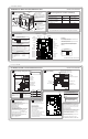
Power Cabling
E
Reserved for Tape Drive
Reserved for
Hard Disk Drives
Shelf 6
FDD
CD-ROM
Hard Disk Drive
Shelf 1
Shelf 2
Shelf 3
Shelf 4
Power Supply
Harness
System
Board
Shelf 5
Shelf 6
Shelf 7
Power Supply
Unit
ATX Connector
When removing the Power Supply,
disconnect its four connectors from
the harness along dotted line. Retain
the other harness.
BP4
P1
BP1
BP1
BP2
BP2
BP3
BP3
P6
P5
P4
P3
P2
© Copyright 2000. Hewlett-Packard Company
Audience Assumptions
This Technical Reference Card is for trained service
personnel. Hewlett-Packard Company assumes you
are qualified in the servicing of computer equipment
and trained in recognizing hazards in products with
hazardous energy levels.
Electrostatic Discharge
To avoid catastrophic or hidden damage to components,
wear a wrist strap and use a static-dissipative work
surface connected to the chassis when handling
components. Use an antistatic service kit, such as
3M 8501/8502/8505 or equivalent.
This information is subject to change without notice
and is provided without warranty.
Tips for Removing
the System Board
G
Note: For complete instructions,
see the Information Assistant on the
HP Documentation CD-ROM.
Key to Mounting Screws
Visible when Cables and Processors
have been Removed.
Snaps
•Unplug Power, Remove Cover
•Retract Feet, Lay Unit on Right Side
•Swing Air Duct Open
•Disconnect All Cables
from System Board
•Take out CPUs (If Only One CPU
Present, Also Remove Terminator
from Second Slot)
•Take out All PCI Cards
•Remove All 7 Screws (See Illustration)
•Grasp and Unsnap the Snaps
at Corners Opposite Back Panel
•Swing Edge Opposite Back Panel Outward
•Slide Board Out Carefully
HP Product No. D9387-80202
HP PN: D9387-80202 BACK SIDE
For additional information, see other side.
Snap
1
3 4 5
6 7
2
Snap
Mass Storage Cabling/Rear LEDs
D
Reserved for
(Optional)
Tape Drive
Reserved for
Hard Disk Drives
Shelf 6
FDD Connector
System Board
Primary IDE
Secondary IDE
SCSI B
SCSI A
Built-in SCSI Terminator
FDD
A
CD-ROM
Hard Disk Drive
(Some Models)
Shelf 1
Shelf 2
Shelf 1
Shelf 4
Shelf 5
Shelf 6
Shelf 7
Power
Receptacle
B
C
Rear LED Indicator
On LAN Connector
Activity Link Indicator
Steady Green-Link Valid
Blinking Green- Activity
on LAN
LAN Speed Indicator
OFF-10Mbps
Steady Yellow-100Mbps
LED LED
Flexible
Disk
Cable
Cables
IDE
CD-ROM
Cable
SCSI
Cable
Part Number
A
B
C
D5183-9849
D5184-9420
D5184-9419
Shelf 2
Shelf 3
HP NetServer E800 Technical Reference Card HP Product No. D9387-80202
Cabinet/Front LEDs
A
System Board
Power Supply
Shelf 1: Flexible Disk
Shelf 2: CD-ROM
Shelf 3: Optional Tape Drive
(Included in Certain Models)
Shelf 4: Hard Disk Drive
(Included in Certain Models)
Shelves 5, 6, 7
Cage for additional HD Drives
Do not operate
without air duct.
Front LED Indicator
Below Shelf 3
System Power Switch
System Power Indicator
Off-System is Off
Solid Green-System is Running
Blinking Green-System is in
Sleep Mode
Hard Drive Activity Indicator
Flashing Yellow-IDE or
SCSI Activity
System Board
C
DIMM Installation
• Use Only HP buffered DIMMs
• Any combination (mix or match) of up to four
each of 128MB, 256MB or 512MB DIMMs
• Order of Installation is Slot 0, 1, 2, 3 with largest
DIMMs installed in the lowest Slot number
For additional information, see other side.
1. IDE CD-ROM
2. FDD
3. Embedded SCSI A
4. Embedded SCSI B
5. PCI 1
6. PCI 2
7. PCI 3
8. PCI 4
9. PCI 5
10. PCI 6
11. PCI 7
Default Boot Order
SCSI (A&B)
Emb LAN
PCI 1
PCI 2
PCI 3
PCI 4
PCI 5
PCI 6
IRQ Sharing
Cautions:
Do not mix CPU types or speeds. Both CPU's must
be the same type and speed.
Terminator is required in secondary CPU slot when
second CPU is not installed.
The Air Duct and all covers and panels must be
in place to provide controlled airflow for system
reliability.
Device
Standard Hard Disk Drive
(Model 9.1 GB)
Standard SCSI Controller
Standard IDE CD-ROM
HP SureStore T20i
HP SureStore DAT 8i or 24i(Bundled)
HP Accessory 4.2 GB HDD or
HP Accessory 18.2 GB HDD or
HP Accessory 36.4 GB HDD
See documentation with each device for further configuration information.
Device Settings
Shelf 4
Shelf 5, 6, 7
Embedded
SCSI ID 0 [Default]
SCSI ID 4 [Default]
SCSI ID 7
SCSI ID 2 [Default]
Shelf 2 Set to Master [Default]
Shelf 3
Shelf 3
For Additional HDD, Set to
Unused SCSI ID
Mass Storage Device Locations and Settings
B
Location in order of
recommendation
HP PN:
D9387-80202
FRONT SIDE
Power
Mouse
Keyboard
CPU 1 Fan
CPU 2 Fan
SCSI A
Status Panel
FDD
LAN
Serial A
Serial B
PCI Slot 1
Video
SVGA
Parallel
DIMM Slots
1 2 30
Prossesor 1
(CPU 1)
Prossesor 2
(CPU 2)
CPU Terminator
Chassis Fan
PCI Slot 2
PCI Slot 3
PCI Slot 4
PCI Slot 5
PCI Slot 6
PCI Slot 7
Not Used
Config
Switch
SCSI B
IDE 1
IDE 2
System Switch Settings
1 2 3 4
On
Off
On = Clear Configuration
On = Clear Password
Off
Unused