
HP Netserver E 45 and E 50 Installation Roadmap

1.Overview of NetServer Features
2. Verify Contents
3. Obtain Release History
4. Connect Monitor, Keyboard and Mouse
5. Preparation
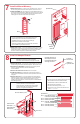
6. Remove the Cover
7. Install Additional Memory
8. Install All Adapter Boards
9. Install Additional Mass Storage Devices
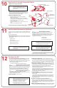
10. Replace the Cover and Connect All Cables
11. Verify Installed Accessories
12. Configure the HP NetServer
HP NetServer Navigator CD-ROM
ESD Warning
Audience Assumptions
Tools Required
This road map is intended for the person who installs, administers,
and troubleshoots LAN servers. Hewlett-Packard Company
assumes that you are qualified in the servicing of computer
equipment and trained in recognizing hazards in products with
hazardous energy levels.
This NetServer contains sensitive electronic devices that can be
damaged by electrostatic discharge (ESD). ESD hazards are a result
of installation or service personnel failing to ground themselves
properly. To be properly grounded, you must use a proper ESD wrist
strap and work surface grounded to the NetServer chassis.
• Screwdrivers: flat 1/4-inch, TORX T15
• Navigator CD-ROM (included)
®
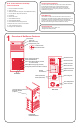
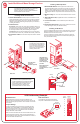
Mouse Connector
Keyboard Connector
Serial A Connector
Serial B Connector
Monitor Connector
Rear Cooling Fan
Parallel Connector
Power Switch
E45-E50Installation Road Map
Table of Contents
Overview of NetServer Features
Rear View
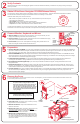
Front View
Front View,
Cover Removed
Front Panel Key Lock
Shelf 1 (Flexible Disk Drive)
Power and
Disk Drive Activity
Shelf 2 (CD-ROM Drive)
Shelf 3 (Tape backup device provided
in certain models)
Shelf 5 (behind fan)
Shelf 6 (behind fan)
Technical Reference Card and
Diagnostic Diskette
(in pouch)
Network
Connector
Locked Position
Unlocked Position
Line Voltage Switch
Power Connector
Factory Seal (located on bottom of chassis)
1
Shelf 4 (Mass storage tray provided)