HP NetServer E 60, LC 3, LH 3/3r, and LPr Processor Upgrade Installation Guide HP Part Number 5969-0074 Printed in March 1999
Notice The information contained in this document is subject to change without notice. Hewlett-Packard makes no warranty of any kind with regard to this material, including, but not limited to, the implied warranties of merchantability and fitness for a particular purpose. Hewlett-Packard shall not be liable for errors contained herein or for incidental or consequential damages in connection with the furnishing, performance, or use of this material.
Contents 1 Introduction ................................................................................................. 1 About This Upgrade Accessory...................................................................... 1 About This Guide........................................................................................... 2 Accessory Kit Contents.................................................................................. 2 Tools ................................................................
Contents Remove the HP NetServer LPr from the Rack............................................. 38 Remove the Cover ...................................................................................... 38 Install the Processor Modules ...................................................................... 39 Removing the Terminator Board.............................................................. 40 Removing the Existing Processor Module................................................
1 Introduction About This Upgrade Accessory Use this accessory kit to upgrade the processors in your HP NetServer E 60, LC 3, LH 3/3r, or LPr, as follows: • Upgrade an HP NetServer E 60, LC 3, LH 3/3r, or LPr by replacing an existing processor module with a higher-speed processor. • Upgrade an HP NetServer E 60, LC 3, LH 3/3r, or LPr by adding a second processor module to a single-processor system. NOTE Use only HP processor modules recommended for your NetServer.
Chapter 1 Introduction CAUTION Do not attempt to use the existing processors or VRMs from the HP NetServer LC II system board. They are not compatible with the HP NetServer LC 3 system board. About This Guide This guide describes the procedure for installing a Pentium II or Pentium III processor module into the HP NetServer E 60, LC 3, LH 3/3r, and LPr. It also describes how to install a voltage regulator module (VRM) into the HP NetServer LC 3, LH 3/3r, and LPr.
Chapter 1 Introduction • HP NetServer E 60, LC 3, LH 3/3r, and LPr Processor Upgrade Guide (this document) Tools CAUTION Components of this accessory kit are sensitive to static electricity and can be easily damaged by improper handling. Read the following information carefully before you handle the accessory components: • Leave the components in the anti-static container until you are ready to install them. • Use an anti-static wrist strap and a grounding mat.
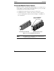
Chapter 1 Introduction Processor Module Form Factors Different form factors of Pentium II and Pentium III processor modules exist, as shown in Figure 1-1. The form factor in this kit lacks the two processor module release latches present in the alternate form factor. • For HP NetServer E 60 or LPr, the form factor is unimportant. • For HP NetServer LC 3 or LH 3/3r, the form factor in this kit requires a processor retaining latch, which is described in Chapter 3, "Installation in LC 3 and LH 3/3r.
2 Preparation Preparation Overview Before you begin to upgrade the processors, you will do the following: • Verify that you have the current release of the HP NetServer Navigator CD-ROM. • View the Readme file on the HP NetServer Navigator CD-ROM to obtain the most current information about this upgrade accessory. If your system BIOS needs updating, you will receive a message saying so. • Update the BIOS, if necessary.
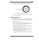
Chapter 2 Preparation rver Navi ga tSe Ne r to HP 2. Compare the version number on the status report with the version number on the HP NetServer Navigator CD-ROM, as shown in Figure 2-1. Version Number XXXX Figure 2-1. CD-ROM Version Number 3. If you do not have the latest version, obtain it as instructed by the ordering information on the status report.
Chapter 2 Preparation ◊ If this message does appear, you must update the BIOS. You will do it after you view the Readme file. 3. Go to the HP NetServer Navigator Main Menu. 4. On the Main Menu, choose Readme File. CAUTION Versions of the HP NetServer Navigator CD-ROM other than the one that shipped with the new processor modules may not contain the appropriate BIOS for these new processor modules.
Chapter 2 Preparation Press to enter SETUP on the display monitor, press the F2 function key. 3. If a password has been set, provide it when prompted. 4. When the Setup Utility menu is displayed, use the left and right arrow keys to select the Configuration menu. 5. On the Configuration menu, use the up and down arrows to highlight Boot Device Ordering, and press ENTER. 6. On the Boot Device Ordering submenu, use the up and down arrows to highlight Hard Drive Priority, and press ENTER. 7.
Chapter 2 Preparation Reconfigure Hard Drive Priority Run the Setup utility again to reconfigure the hard drive priority, as follows: 1. When the NetServer restarts, press the F2 function key at the prompt to run the Setup utility. 2. If a password has been set, provide it when prompted. 3. When the Setup Utility menu is displayed, use the left and right arrow keys to select the Configuration menu. 4. On the Configuration menu, use the up and down arrows to highlight Hard Drive Priority, and press ENTER.
3 Installation in LC 3 and LH 3/3r Installation Overview NOTE If you install two processor modules, use processor upgrade kits with the same HP product number. If you add a second processor module, match it to the existing processor module. (Your HP reseller can advise you about matching processor modules.) Add the new processor module to the secondary processor position. To avoid flexing the system board, remove it before upgrading processor modules in HP NetServer LC 3 and LH 3/3r. Do the following: 1.
Chapter 3 Installation in LC 3 and LH 3/3r Table 3-1 summarizes differences among the operations required for various types of upgrades. It also lists the section in this chapter that describes each operation. Table 3-1.
Chapter 3 Installation in LC 3 and LH 3/3r Disconnect the NetServer 1. Bring down the network properly. If necessary, shut down the network operating system. 2. Turn off power to the HP NetServer and the monitor. 3. Disconnect all cables, as follows: ◊ DISCONNECT THE AC POWER CORD and all telephone cables from the HP NetServer. ◊ Disconnect all cables attached to the system board at the rear of the NetServer (such as mouse, keyboard, and other cables).
Chapter 3 Installation in LC 3 and LH 3/3r Remove the Front Bezel and Covers Refer to your NetServer documentation to remove the front bezel and covers to gain access to the system board to remove it. If your NetServer is mounted in a rack enclosure, also refer to your rack documentation. WARNING Do the following to prevent the rack enclosure from tipping over: • Extend the anti-tip foot, or verify that the anti-tip feature is installed. • Verify that the leveler feet are lowered.
Chapter 3 Installation in LC 3 and LH 3/3r CAUTION Lay the system board component-side up on a static-dissipating work surface with the metal crosspiece on the top rear corner of the system board extending off the work surface, as shown in Figure 3-1. Place Crosspiece Off Work Surface Static-Dissipating Work Surface Figure 3-1.
Chapter 3 Installation in LC 3 and LH 3/3r Install the Processor Modules and VRMs See Figure 3-2 for the location of the processor module positions, VRM sockets, and system switches on the system board. Secondary Processor Module Position Primary Processor Module Position Socket for VRM for Secondary Processor System Switches Table of System Switch Settings Socket for VRM for Primary Processor Figure 3-2.
Chapter 3 Installation in LC 3 and LH 3/3r Removing the Terminator Board If your system has one processor, a terminator board is installed in the upper (secondary) processor position. You must remove the terminator board before installing a processor module into this position. (See Figure 3-3). 1. Squeeze together the two retaining latches on the terminator board. 2. Pull the terminator board out of the slot. 3. Save the terminator board for future use.
Chapter 3 Installation in LC 3 and LH 3/3r Removing the Existing Processor Module If you are upgrading an existing processor module, you must first remove the existing processor module. Refer to Figure 3-4 to determine whether the processor module you are removing has a processor retaining latch. Then refer to the appropriate removal instructions in the following sections. Processor Retaining Latch Figure 3-4.
Chapter 3 Installation in LC 3 and LH 3/3r Removing a Processor Module Without a Processor Retaining Latch To remove a processor module that does not have a processor retaining latch: 1. Press in on each processor module release latch until it remains in (see Figure 3-5). If the latch does not stay in, you must hold it in while removing the module. Processor Eject Lever Processor Mounting Bracket Processor Module Release Latch (Two Places) Figure 3-5.
Chapter 3 Installation in LC 3 and LH 3/3r 3. Remove the processor module from the mounting bracket assembly. Removing a Processor Module With a Processor Retaining Latch To remove a processor module that HAS a retaining latch: 1. Squeeze the two tabs on the outer edge of the processor retaining latch, as shown in Figure 3-6. Disengage the two retaining hooks from the other side of the processor ejector lever. Disengage Two Hooks from Processor Ejector Lever Processor Ejector Lever Figure 3-6.
Chapter 3 Installation in LC 3 and LH 3/3r 2. Lift up on the processor ejector lever until the processor pops out of the processor slot (see Figure 3-7). Processor Ejector Lever Processor Mounting Bracket Figure 3-7. Removing a Processor Module With a Retaining Latch CAUTION Do not move the processor ejector lever beyond its limit (about 25-30 degree angle from the original position). The ejector lever may break if forced. 3. Remove the processor module from the mounting bracket assembly.
Chapter 3 Installation in LC 3 and LH 3/3r Installing Processor Modules To install a processor module: 1. Orient the retaining latch to the processor module as shown in Figure 3-8. Processor Module Processor Retaining Latch Edge Connector Hooks to Engage Processor Module Figure 3-8.
Chapter 3 Installation in LC 3 and LH 3/3r 2. Press the retaining latch firmly onto the processor module until two hooks engage the processor module, as shown in Figure 3-9. Hook Detail Shows Hook Engaged to Processor Module Hook (Two Places) Figure 3-9.
Chapter 3 Installation in LC 3 and LH 3/3r 3. Orient the processor module (with its retaining latch mounted) to the correct processor position (slot), as shown in Figure 3-10. Processor Module Processor Mounting Bracket Secondary Processor Position Primary Processor Position Figure 3-10.
Chapter 3 Installation in LC 3 and LH 3/3r 4. Slide the processor module into the processor mounting bracket, and press it firmly into the slot, as shown in Figure 3-11. The processor ejector lever rotates during this insertion. Hooks to Engage Processor Ejector Lever Processor Mounting Bracket Processor Ejector Lever Secondary Processor Position Primary Processor Position Figure 3-11.
Chapter 3 Installation in LC 3 and LH 3/3r 5. Verify that the processor ejector lever has rotated over the edge of the processor retaining latch, as shown in Figure 3-12. If the ejector lever is not fully rotated, gently push it into place. If the ejector lever does not rotate easily over the edge of the processor retaining latch, the processor module is not fully inserted into its slot. In that case, press firmly on the processor module to seat it.
Chapter 3 CAUTION Installation in LC 3 and LH 3/3r The processor ejector lever secures the processor module in its slot. Verify that the ejector lever is completely rotated into the position shown in Figure 3-12. Verify that two hooks on the processor retaining latch engage the ejector lever. • Do not force the ejector lever into place. • If necessary, repeat Steps 4-6.
Chapter 3 Installation in LC 3 and LH 3/3r Installing a VRM One voltage regulator module (VRM) must be installed for each processor module installed. If only one processor module is installed, a VRM must be installed in the primary (lower) VRM socket, next to the primary processor. To install a VRM: 1. Orient the VRM as shown in Figure 3-13. The component side of the VRM faces the center of the system board. Do not touch the components on the VRM.
Chapter 3 Installation in LC 3 and LH 3/3r 2. Holding the VRM as shown in Figure 3-14, press it firmly into the VRM socket on the processor board. Be sure to press only on the thin edge of the main VRM board when inserting the VRM into the socket. Caution: Do not push here Main VRM Board VRM Release Latches (shown in open position) VRM Socket Figure 3-14. Installing a VRM in HP NetServer LC 3 and LH 3/3r CAUTION When installing the VRM, push only on the edge of the main VRM board (see Figure 3-14).
Chapter 3 CAUTION Installation in LC 3 and LH 3/3r Do not push in on the VRM release latches; the release latches will close automatically when the VRM is installed completely. If the VRM is not installed completely, pushing in on release latches may damage the latches, the socket, or the VRM. Installing Terminator Board for Single-Processor NetServer A single-processor system board should already have a terminator board (terminating resistor module) installed in the secondary processor position.
Chapter 3 Installation in LC 3 and LH 3/3r Terminator Board Retaining Latches Terminator Board Secondary Processor Position Primary Processor Module Figure 3-15. Install the Terminator Board in a Single-Processor HP NetServer LC 3 or LH 3/3r 2. Insert the terminator board into the upper (secondary) processor position. 3. Verify that the terminator board is installed completely in the slot. When the terminator board is installed completely, the retaining latches (see Figure 3-15) will be closed.
Chapter 3 Installation in LC 3 and LH 3/3r Setting System Switches For processor upgrades to a clock speed greater than 450 MHz, examine the table next to the system switches in the upper right corner of the system board, as shown in Figure 3-16. If 500 MHz is not listed in the table, attach the label with system switch settings to the system board. To do so, peel the backing off the label to expose the adhesive, and affix the label to the system board on the table of system switch settings.
Chapter 3 Installation in LC 3 and LH 3/3r CAUTION Processor modules are designed to operate at only one speed. This speed is printed on the module. Do not set the system switches to any speed other than that speed labeled on the module. Setting the processor speed to another speed may result in unreliable or intermittent performance. Data integrity may also be placed at risk if processors are operated at speeds other than the speed specified on the processor module.
4 Installation in E 60 and LPr Installation Overview NOTE If you install two processor modules, use processor upgrade kits with the same HP product number. If you add a second processor module, match it to the existing processor module. (Your HP reseller can advise you about matching processor modules.) Add the new processor module to the secondary processor position. Upgrade processors in HP NetServer E 60 or LPr with the system board in the NetServer, as follows: 1.
Chapter 4 Installation in E 60 and LPr Table 4-1 summarizes differences among the operations required for various types of upgrades. It also lists the section in this chapter that describes each operation. Table 4-1.
Chapter 4 Installation in E 60 and LPr Disconnect the NetServer 1. Bring down the network properly. If necessary, shut down the network operating system. 2. Turn off power to the HP NetServer and the monitor. 3. DISCONNECT THE AC POWER CORD and all telephone cables from the HP NetServer. WARNING Before removing the cover, always disconnect the power cord and unplug telephone cables. Disconnect telephone cables to avoid exposure to shock hazard from telephone ringing voltages.
Chapter 4 Installation in E 60 and LPr Remove the HP NetServer LPr from the Rack For HP NetServer LPr, refer to your NetServer documentation and rack documentation to remove the front bezel and remove the NetServer from the rack. WARNING Do the following to prevent the rack enclosure from tipping over: • Extend the anti-tip foot, or verify that the anti-tip feature is installed. • Verify that the leveler feet are lowered.
Chapter 4 Installation in E 60 and LPr Install the Processor Modules See Figure 4-1 or 4-2 for the location of the processor positions and system switches on the system board. Secondary Processor Position Primary Processor Module System Switches Figure 4-1. HP NetServer E 60 System Board Secondary Processor VRM Socket for Module Position Secondary Processor System Switches Primary Processor Module VRM for Primary Processor Figure 4-2.
Chapter 4 Installation in E 60 and LPr If any accessory boards block access to the processors (or VRM positions in the HP NetServer LPr), refer to your NetServer documentation to remove those accessory boards. Removing the Terminator Board If your system has one processor, a terminator board is installed in the secondary processor position. You must remove the terminator board before installing a processor module into this slot. (See Figure 4-3). 1.
Chapter 4 Installation in E 60 and LPr Removing the Existing Processor Module If you are upgrading an existing processor module, you must first remove the existing module from the slot. To remove a processor module: 1. Slide the blue plastic release levers to free the processor module, as shown in Figure 4-4. 2. Remove the processor module from the processor mounting bracket. Slide Levers to Free Processor Module Processor Module Processor Mounting Bracket Figure 4-4.
Chapter 4 Installation in E 60 and LPr Installing Processor Modules To install a processor module, refer to Figure 4-5 and do the following: 1. Slide the blue plastic release levers toward the center of the board. 2. Orient the processor module to the correct processor position. The heat sink faces toward the center of the system board. 3. Slide the processor module into the processor mounting bracket and press it firmly into the slot until it is seated completely.
Chapter 4 CAUTION Installation in E 60 and LPr If the NetServer has only one processor module, it must be installed in the primary processor position, and a terminator board must be installed in the secondary processor position. If you add a second processor, leave the original processor in the primary position, and add the new processor to the secondary position. Installing a VRM in HP NetServer LPr NOTE The HP NetServer E 60 does not require installation of voltage regulator modules (VRMs).
Chapter 4 Installation in E 60 and LPr To install a VRM in an HP NetServer LPr: 1. Orient the VRM as shown in Figure 4-6. The component side of the VRM faces the center of the system board. Do not touch the components on the VRM. Secondary Processor Module Do Not Touch VRM Components VRM Secondary VRM Slot Secondary Processor Position Figure 4-6. Installing a VRM in an HP NetServer LPr 2. Gently press the VRM down into the socket until it is seated completely.
Chapter 4 Installation in E 60 and LPr CAUTION Do not push in on the VRM release latches; the release latches will close automatically when the VRM is installed completely. If the VRM is not installed completely, pushing in on release latches may damage the latches, the socket, or the VRM. Installing Terminator Board for Single-Processor NetServer A single-processor system board should already have a terminator board installed in the secondary processor position.
Chapter 4 Installation in E 60 and LPr 2. Insert the terminator board into the secondary processor position. 3. Verify that the terminator board is installed completely in the slot. Setting System Switches After installing processors, verify that the system switches are set to the correct processor clock speed (frequency). If the switches are not set correctly, set them accordingly. To set the system switches: 1. Locate the system switches on the system board (see Figure 4-1 or 4-2). 2.
Chapter 4 Installation in E 60 and LPr CAUTION Never operate the NetServer, even for a short time, without first installing all covers and the front bezel. Operating the system without all covers in place reduces critical cooling airflow over some components, such as hard disk drives, circuit boards, and processor modules. Operating the system without all covers in place may result in failure of these components.
5 Verification Verification Overview HP DiagTools is the offline diagnostic program that you will use to verify the processor upgrade. You will run it from a flexible diskette that you will make from the HP NetServer Navigator CD-ROM. To verify the upgrade, do the following: • Start HP NetServer Navigator, and go to the NetServer Utilities menu. • Use HP NetServer Navigator to create an HP DiagTools flexible diskette. • Run HP DiagTools from the flexible diskette to verify the upgrade.
Chapter 5 Verification NOTE As the NetServer starts, the display monitor or the LCD display on the NetServer lists all the processors that are recognized. If you added a second processor, it may not be recognized until you reinstall the NOS or install a NOS module or other NOS component later in this chapter. 2. When HP NetServer Navigator starts, go to the Main Menu. If the system fails to start, follow the instructions on the screen. 3.
Chapter 5 Verification NOTE HP DiagTools does not support use of the mouse. Use the keyboard’s arrow and tab keys. If you find that you cannot use the arrow and tab keys, use the function keys as instructed on the screen. If HP DiagTools does not start, refer to the HP NetServer DiagTools Error Reference and User Guide. 2. When the next screen appears, press the F2 function key to continue with HP DiagTools and start the Configuration Detection tests. 3.
Chapter 5 Verification HP DiagTools then reports whether the Basic System Test was passed. Record the hardware inventory and the Basic Test results by creating a Support Ticket text file. NOTE ◊ To create a Support Ticket, refer to the HP NetServer DiagTools Error Reference and User Guide, and write the Support Ticket to a flexible diskette. If the Basic System Test was passed, the upgrade has been verified. Do the following: a. Press the F3 function key to exit HP DiagTools. b.
Chapter 5 Verification 6. If the Basic System Test was failed again after you took the corrective actions determined in Step 5, run Advanced System Tests as described in the HP NetServer DiagTools Error Reference and User Guide. Run the System and Memory tests as a batch. NOTE Do not use the Erase Errors List command. It would erase the error list that you will use to create a Support Ticket. 7.
Chapter 5 Verification About the Support Ticket The Support Ticket is a text file you can create in HP DiagTools. It lists the hardware detected and the test results from HP DiagTools. The HP NetServer DiagTools Error Reference and User Guide describes the Support Ticket and how to create it. • When you create a Support Ticket, you may be given a choice of destinations for the file. You will be shown its filename and location.
A Warranty and Support The hardware warranty below applies to components purchased as accessories. If your component was factory installed as part of an HP NetServer model, refer to the HP NetServer Warranty and Service/Support Booklet provided with your system documentation for the warranty limitations, customer responsibilities, and other terms and conditions.
B Regulatory Information For regulatory information pertaining to this HP accessory, please refer to the regulatory section of the installation guide for the NetServer in which this accessory is installed.
Index A Accessory kit contents, 2 Advanced System Tests, 53 B Basic System Test, 51 BIOS Update Utility, 8 BIOS version, 6 BIOS, updating, 7, 8 Boot device order, 7 C Caution BIOS versions, 7 cover and bezel installation, 33, 47 primary processor installation, 24, 43 processor ejector lever, 19, 21 processor module installation, 27 processor module speed, 33, 46 static electricity, 3, 13, 37 VRM installation, 29, 44 VRM release latches, 30, 45 Configuration Advisor, 54 Configuration Detection tests, 51 Conn
Index Installing covers, 33, 46 front bezel, 33 in HP NetServer E 60, 47 in HP NetServer LC 3, 11–33 in HP NetServer LH 3/3r, 11–33 in HP NetServer LPr, 47 NOS, 54 processor module, 22, 42 terminator board, 30 VRM, 28, 43 Introduction, 1–4 L Label Pentium III, 33, 47 system switch settings, 32 N NetServer date and time, 54 Network Operating System Installation Instructions, 54 NOS installation, 54 P Pentium III label, 33, 47 Preparation, 9 Preparation overview, 5 Processor ejector lever, 19, 21, 26 Process
Index U Utilities BIOS Update Utility, 8 HP DiagTools, 50 Setup, 7, 9 V Verification, 49–54 Verification overview, 49 Voltage Regulator Module (VRM), 28, 43 VRM release latches, 29 W Warning anti-tip, 14, 38 shock hazard, 13, 37 Warranty hardware accessories limited, 55 Warranty, hardware, 55 61