HP A3661B Model 30/FC High Availability Disk Array Supplement to HP NetServer Microsoft Cluster Installation Guide July 1, 1998
Notice The information in this document is subject to change without notice. Hewlett-Packard Company makes no warranty of any kind with regard to this material, including, but not limited to, the implied warranties of merchantability and fitness for a particular purpose. Hewlett-Packard shall not be liable for errors contained herein or for incidental or consequential damages in connection with the furnishing, performance, or use of this material.
Contents OVERVIEW .............................................................................................................................................................................. 4 INTRODUCTION ........................................................................................................................................................................ 4 OPERATING SYSTEM ....................................................................................................................
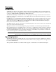
Overview Introduction An HP NetServer cluster provides a reliable, cabinet-mounted, increased-availability solution for critical applications. The basic cluster consists of two HP NetServer systems coupled to an HP Fibre Channel Arbitrated Loop (FC-AL) hub connected to an HP A3661B Model 30/FC High Availability Disk Array. The HP Model 30/FC High Availability Disk Array is a high capacity mass storage device that can reside in the same cabinet (also called a rack) as the HP NetServer and an HP FC-AL hub.
1 – What’s Needed? Fibre Channel IDs During HP Model 30/FC High Availability Disk Array installation, be prepared to supply one Fibre Channel ID for each FC-AL connection between an HP FC-AL hub and an SP on an HP Model 30/FC High Availability Disk Array. See part 3, step 5, table 2 of this guide for a list of Fibre Channel IDs. Hardware Compare the hardware you have with ordering documentation, such as the parts lists created by Order and Rack Assistants.
2 – HP NetServer Hardware Setup Install the FC I/O Adapter 1. Install the FC I/O Adapter in the PCI Slot Install the FC I/O adapter in an appropriate PCI slot as specified in the Configuration Guide for the HP NetServer. Installation steps are shown for both vertical and horizontal installations. Install a FC I/O adapter in each HP NetServer in the cluster. a. Make sure the HP NetServer is powered down. b. Remove the chassis cover. c. Locate the correct PCI expansion slot in the system. d.
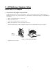
2. Install the GBIC a. Locate the short-wave GBIC (Gigabit Interface Converter) included in the FC I/O adapter kit. b. Install the GBIC into the receptacle on the FC I/O adapter (see figure 2). NOTE The GBIC can only be installed one way, because the GBIC and guide rails inside the FC I/O adapter receptacle are keyed. Installing the GBIC Figure 2. GBIC Module Do not attach Fibre Channel cables to the FC I/O adapter at this time. Also, do not reboot the HP NetServers at this time.
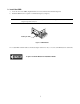
3 – Shared Storage Hardware Setup Install the HP FC-AL Hub 1. Unpack the HP FC-AL Hub a. Unpack and inspect the HP FC-AL hub for any damage that may have occurred during shipment. b. Save the boxes and packing materials in case there is damage or anything needs to be reshipped at a future date. c. Make sure all items shown in figure 3 are present. Contact your sales representative if items are missing.
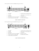
The front panel of the short-wave hub (HP A3724A) appears as follows: 2 4 1 10 3 6 7 5 8 9 1. Power LED 6. 10Base-T Port (reserved for future use) 2. Fault LED 7. MAC address (reserved for future use) 3. Reset button 8. RS-232 port 4. Fibre Channel connector (Port 1 indicated) 9. AC power connector 5. FC-AL short-wave ports and port LEDs 10. Port LED (Port 1 indicated) Figure 4.
2. Verify HP FC-AL Hub Operation Test the HP FC-AL hub and verify that it operates before mounting it in the cabinet (also called a rack). a. Perform a self-test by connecting the short-wave loopback cable to a short-wave hub port, plugging the power cord into the HP FC-AL hub, and then plugging the power cord into a power receptacle. The short-wave loopback cable includes “50/125” as part of the identification information printed on the cable.The HP FC-AL hub does not have a power switch.
3. Mount the HP FC-AL Hub into the Cabinet The HP FC-AL hub mounts into the HP E3662A or E3662B 2.0m high, 19-inch wide, 220VAC, EIA cabinet (also called a rack). The following procedure describes mounting an HP FC-AL hub with its front panel facing the rear of the cabinet. The front of the HP FC-AL hub contains the 10 Fibre Channel connectors. a. Record the serial number, located on the bottom of the HP FC-AL hub, before installing the HP FC-AL hub into the cabinet. b.
g. Set the HP FC-AL hub on the cabinet. Align the hole in each mounting ear bracket with the holes in the assembled rail, nut, and column, and insert a 10-32 x .625 machine screw. Securely tighten the screws (see figure 7). Figure 7. Installing the HP FC-AL hub into the cabinet h. The plenum shroud is a back cover that slides onto the HP FC-AL hub. Set the plenum shroud on the front side of the cabinet. Align the holes in the brackets with the holes in the assembled rails and outer posts. i.
Figure 9. HP FC-AL hub correctly installed in a cabinet If cascading HP FC-AL hubs are being used, install the second HP FC-AL hub, following the same steps used in installing the first HP FC-AL hub. Do not attach Fibre Channel cables or power cords to the HP FC-AL hub at this time. Also, do not power up the cabinet at this time.
Install the HP Model 30/FC High Availability Disk Array 1. Check Power Requirements Refer to the disk array DC power requirements in the Reference chapter of the Hewlett-Packard Model 30/FC High Availability Disk Array Service Manual (part number A3661-90002) to make sure the installation site meets these requirements. The HP Model 30/FC High Availability Disk Array uses 200VAC to 240VAC nominal; 110VAC is not supported.
The HP Model 30/FC High Availability Disk Array is rated to draw approximately 5amps at 230VAC steady state current for normal operation. However, when powered on, the disk array draws a heavy in-rush (surge) current (up to 115 amps for 10 to 12 ms) that could trip standard industrial circuit breakers.
i. Remove the disk array’s front bezel by grasping its sides and pulling straight out. If the bezel is difficult to remove, use a small standard screwdriver to carefully loosen the bezel at its four outside corners. To remove front bezel, grasp the sides of the panel and pull straight out. To install front bezel, press panel onto ballstuds. Ballstud Figure 10. Removing the front bezel 3. Prepare the Cabinet The HP Model 30/FC High Availability Disk Array requires 11 EIA units of space in the cabinet.
c. Attach the mounting rails to the cabinet as shown (see figure 11). – Determine the location in the cabinet where the disk array is to be mounted. The disk array should be mounted in the lowest position available in the cabinet. – Install two clip nuts (A in figure 11) over the two holes in the front and back cabinet columns at the height where the left rail is to be mounted. – Mount the left rail by inserting the tabs at the front and rear of the cabinet (B in figure 9).
4. Install the HP Model 30/FC High Availability Disk Array in the Cabinet a. Remove the fan pack from the back of the disk array. – Grasp the fan pack handle. – Press the lock/unlock button and hold it down. – Carefully swing the fan pack down. – Press the release latches in the direction shown. – Pull the fan pack away from the chassis. CAUTION Do not lift a fan pack by its handle as doing so can damage the fan pack.
b. Remove the battery backup unit (BBU) from the back of the disk array. – Locate the BBU. It is above the power supply units. – Grasp the BBU by inserting your thumbs in the holes and your forefingers into the latches. – Slide the latches inward and hold. – Pull the BBU out of the chassis. Back of storage system SP B SP A BBU BBU Figure 13. Location of the BBU CAUTION Use caution when removing the BBU. It is very heavy. Figure 14.
c. Remove the power supply units from the back of the disk array – Grasp a power supply unit by its handle. – Squeeze the latch toward the handle. – Pull the power supply unit out of the chassis. – Repeat for the other power supply units. Figure 15.
d. Mount the disk array chassis into the cabinet. WARNING The disk array is very heavy. Use extreme care when moving or lifting it. At least two persons are needed to lift and safely install a disk array into a cabinet. CAUTION The disk array must be installed so that opening the fan pack door does not interfere with any plug on the cabinet PDU, any cables, any PDUs, or any other devices. – Slide the chassis onto the rails and into the cabinet.
e. Unpack and install the disk modules. CAUTION Handle disk modules very carefully as they can be damaged easily by shock and vibration. Strap the ESD wrist strap to your wrist and ground it to the disk array chassis (or suitable ground). Place the disk module on an ESD conductive sheet when it is removed from its carton. Use ESD kit P/N 5182-4119 (supplied with each disk array). Make sure each disk module’s label, which shows its slot ID (A0, for example), is present.
f. Replace the power supply units. – Locate the slot where the power supply unit is to be installed. – Slide each power supply unit into its slot while squeezing the latch until it engages the connector. – Press firmly until the power supply unit seats fully into the chassis. Figure 18. Replacing a power supply unit g. h. Replace the BBU. – Locate the slot where the BBU is to be installed. – Slide the BBU into the slot until it engages the backplane connector.
i. Reinstall trim. – Install the 1/2 U filler panel (part number A3661-00003) to the bottom of the disk array’s front bezel using four of the screws (part number 2680-0273) from the hardware mounting kit. – Reinstall the disk array’s front bezel. – Reinstall any trim removed from the cabinet and close the cabinet doors. Do not power up the cabinet at this time. 5.
Table 2 – Fibre Channel Addresses FC address (Loop ID) FC address (Loop ID) FC address (Loop ID) (hexadecimal) (decimal) (hexadecimal) (decimal) (hexadecimal) (decimal) 00 01 02 03 04 05 06 07 08 09 0A 0B 0C 0D 0E 0F 10 11 12 13 14 15 16 17 18 19 1A 1B 1C 1D 1E 1F 20 21 22 23 24 25 26 27 28 29 2A 0 1 2 3 4 5 6 7 8 9 10 11 12 13 14 15 16 17 18 19 20 21 22 23 24 25 26 27 28 29 30 31 32 33 34 35 36 37 38 39 40 41 42 2B 2C 2D 2E 2F 30 31 32 33 34 35 36 37 38 39 3A 3B 3C 3D 3E 3F 40 41 42 43 44 45 46
4 – Cluster Cabling and Setup 1. Plan the HP FC-AL Hub Connections The HP NetServers should be powered down when making the FC-AL connections to the FC I/O adapters. Power down the HP NetServers if they are not already powered down. The HP Model 30/FC High Availability Disk Array and the cabinet should still be powered down at this time. CAUTION Incorrect wiring can lead to problems, such as devices left off the loop and inaccessible by the HP NetServer. Follow the guidelines below before starting. a.
NOTE To protect hub ports, port covers should remain installed in all unused ports. 3. Connect Cascading HP FC-AL Hubs If using cascading hubs, connect the two HP FC-AL hubs to each other. • If connecting short-wave hubs, refer to figure 28. • If connecting long-wave hubs, refer to figure 29. – When installing long-wave cascading hubs (HP A4839A), make sure the long-wave port (Port 10) is connected only to the long-wave port (Port 10) on the other long-wave hub. 4.
5. Connect the HP Model 30/FC High Availability Disk Array to the HP FC-AL Hub The external Fibre Channel connectors link the disk array to an HP FC-AL hub through fiber optic cables. These connectors are located at the back of the disk array, on the Fibre Channel Interconnect (printed circuit assembly). The Fibre Channel connectors are located above the SPs. One Fibre Channel connector is associated with each SP.
Figure 26.
Figure 27.
6. Verify FC-AL Cabling Correct cabling example, HP FC-AL short-wave hub (HP A3724A) In a cascaded configuration of HP FC-AL short-wave hubs, use a short-wave cable to connect any port on the first HP FC-AL hub to any port on the second HP FC-AL hub. In the following example, Port 1 on Hub A connects to FC-AL Device 1; Port 10 of Hub A connects to Port 1 of Hub B; and Port 10 on Hub B connects to FC-AL Device 2. Any shortwave FC-AL device or hub can connect to Port 10 of a short-wave hub.
Incorrect cabling examples Do NOT cable together two ports on the same HP FC-AL hub. Ports between the two connections will be eliminated from the FC-AL loop. Figure 30. Incorrect cabling example: connected ports on the same HP FC-AL hub Do NOT leave cables that are connected to the HP FC-AL hub disconnected at the opposite end of the cable. Figure 31. Incorrect cabling example: disconnected cable Do NOT attach more than one cable between any two HP FC-AL hubs. Figure 32.
Nonsupported cabling example Connecting an HP FC-AL hub to more than one other HP FC-AL hub is NOT a supported configuration. Figure 34. Non-supported cabling example: more than two HP FC-AL hubs connected Do not attach power cords or power up the disk array or the cabinet at this time. To part 4 of the HP NetServer Installation Guide.
5 – HP NetServer Software Setup To part 5 of the HP NetServer Installation Guide.
6 – Shared Storage Software Setup Install the Fibre Channel Driver on Windows NT The Hewlett-Packard Model 30/FC Disk Array and the cabinet should be powered down at this time. To install the Fibre Channel driver Windows NT, perform the following steps on each HP NetServer in the cluster: a. Power up the HP NetServer if it is not already powered up. b. Start Windows NT if it is not running and log into an account with administrative privileges. c.
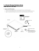
Power Up the HP Model 30/FC High Availability Disk Array 1. Connect the Disk Array’s Power Cord NOTE The correct right-angle power cord must be used. If an incorrect power cord is used, the fan pack cannot be opened without powering down the disk array and disconnecting the power cord. a. Make sure the disk array’s power switch is in the off position, then connect the correct right-angle power cord to the disk array. b.
4. Power Up the Disk Array Turn on the disk array’s power by setting the POWER switch on the back of the unit to ON. The green POWER-ON LED on the front of the disk array will light up and the fans will rotate. On a disk array fully loaded with 30 disk modules, allow 8 to 10 minutes for all the disk modules to spin up. If the BUSY LEDs on the disk drive modules do not light up, check that the disk array’s power cord is properly installed and connected to the cabinet’s PDU.
Install the HP Model 30/FC High Availability Disk Array Software The HP Model 30/FC High Availability Disk Array software consists of the following host-resident utility: • ArrayGUIdeTM ArrayGUIde is a software tool for managing HP Model 30/FC High Availability Disk Arrays connected to HP NetServers. ArrayGUIde consists of a graphical user interface (GUI), called Arraymgr, and a storage system agent, called Agent.
Set the HP Model 30/FC High Availability Disk Array Operating Mode The disk array is shipped from the factory with auto-trespass, which is one of the host mode parameters, turned on. Auto-trespass must be turned off for the disk array to operate correctly on the Microsoft Windows NT operating system. 1. Turn off Auto-Trespass a. Make sure that ArrayGUIde has been installed onto the HP NetServers. b. From the Start bar, select Programs. b. Click Windows NT Explorer. c. Double-click Program Files. d.