
HP Netserver High Availability SPOFless MSCS Cluster Solution

white paper
4
HP
NetServer DocumentationNetServerNetserver
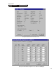
FC Array Controller Firmware
The HP FC array controllers must have the firmware version 5.49-00 installed. The firmware
version can be verified by using the FC Array Assistant. Since the RS/12FC firmware is
independent of the operating system installed on the Netservers, the same firmware is used for
both Windows
®
2000, and Windows NT
®
.
Network Interface Cards
The driver version Hptxnt5.sys version 4.02.27.0 was used for testing on the Windows® 2000
Advanced Server platform. Earlier drivers may work, however they have not been tested.
Supported HP Solutions
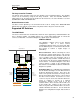
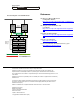
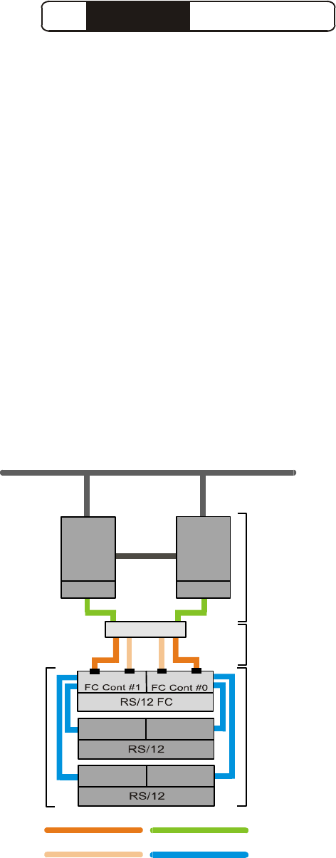
The SPOF Model
The cluster solution based on the RS/12FC, which has been supported by Hewlett-Packard in the
past, is known as SPOF. The SPOF solution uses a single Fibre Channel hub to connect two
servers to an RS/12FC. A functional diagram of a SPOF cluster is shown below.
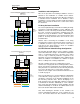
SPOFless Models
The SPOFless solution comes in two different
configurations. One is a direct connect
configuration, while the other uses a pair of FC hubs
and an additional pair of connections between hubs
and storage to achieve a higher degree of
redundancy.
Direct Connection: When connecting the server
directly to the shared storage device, only one port
of each Fibre Channel array controller is used. In the
case of a failure of any one component, such as a
cable, HBA, FC array controller or SCSI interconnect
on the storage side, the cluster software will initiate a
cluster failover. A functional diagram of the direct
connect solution is shown on the following page.
Note that the cascaded RS/12 cabinets shown in the
diagram are optional.
Redundant Hubs: The redundant hub configuration
has two distinct advantages over the Direct Connect
method of attaching the storage. First, due to the
nature of the optical connection, the storage can be
placed much further away from the servers than in
the direct connect solution. Second, the use of the
second set of ports on the FC controllers allows the
cluster to continue to operate at a reduced
performance capacity in the event of an FC
controller failure. This is because failover will occur
on the storage side. However, in the event of the
failure of any of the Fibre Channel cables, the cluster
software will initiate the failover. See the functional
diagram for a configuration using FC hubs shown on
page 5.
Cluster
Server
#1
FC HBA
Cluster
Server
#2
FC HBA
Private
Network
Public Network
Port 1 Port 0
Port 1
Port 0
SCSI #2
SCSI #1
SCSI #2
SCSI #1
6 Port FC Hub
Copper Fibre Active
Copper Fibre Passive
Optical or Copper Fibre
SCSI Cable
Failure
Causes
Application
Failover
Cluster
Failure
Failure
Causes
Decreased
Performance
External
Shared
Storage
Functional Diagram of the SPOF Cluster