HP NetServer LH 3r Installation Guide for Compaq® 4000/7000 Racks HP Part Number 5967-5208 Printed in July 1998
Notice The information contained in this document is subject to change without notice. Hewlett-Packard makes no warranty of any kind with regard to this material, including, but not limited to, the implied warranties of merchantability and fitness for a particular purpose. Hewlett-Packard shall not be liable for errors contained herein or for incidental or consequential damages in connection with the furnishing, performance, or use of this material.
Contents 1 Introduction ................................................................................................. 1 HP NetServer LH 3r – Compaq Rack Precautions ......................................... 4 2 Overview ...................................................................................................... 5 3 Installation ................................................................................................... 7 Preparation.......................................................
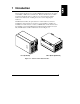
1 Introduction This document describes how to mount an HP NetServer LH 3r into a Compaq model 4000- or 7000-series rack enclosure. Refer to the HP NetServer LH 3r Road Map and the HP NetServer LH 3/3r User Guide that came with the NetServer for instructions on adding accessories to and configuring the NetServer. ® The HP NetServer LH 3 (the pedestal version of this NetServer) cannot be installed in a rack enclosure.
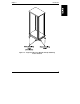
Chapter 1 Introduction WARNING To prevent the rack from tipping over and causing equipment damage or bodily injury, be sure that the stabilizing, anti-tip feature is installed on this rack enclosure (see Figure 1-2). WARNING To prevent the rack from tipping over and causing equipment damage or bodily injury, do not extend more than one piece of equipment at a time out of the front of the rack enclosure.
Chapter 1 Introduction Figure 1-2.
Chapter 1 Introduction HP NetServer LH 3r – Compaq Rack Precautions CAUTION If this NetServer is not installed according to these instructions, damage to the NetServer or accessories may result. Damage due to improper installation is not covered by the HP Warranty. Observe the precautions listed in this section to maintain the NetServer’s reliability.
2 Overview The steps required to install the NetServer in the rack are summarized below: NOTE This is only a summary; detailed instructions are provided on the following pages.
Chapter 2 Overview Terms used in this document are defined in the table below. Term 6 Definition Bar nut Short, threaded bar used behind slide mounting flanges. Used in place of individual nuts to mate with slide mounting screws. Rack nut Single nut designed to clip behind the rack column and accept a screw through the hole in the column. Slide Extendible side bracket which is attached to the rack chassis columns on which the NetServer is mounted.
3 Installation This section contains detailed instructions for installing an HP NetServer LH 3r in certain models of Compaq rack enclosures. Preparation Before beginning the installation of the NetServer into the rack, you must prepare the rack and the NetServer. Determine the location at which the NetServer is to be installed in the rack enclosure. Mark the bottom and top of this location on the rack columns. The HP NetServer LH 3r measures 8 EIA units tall.
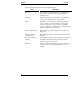
Chapter 3 Installation 22nd 20th 22nd 20th (At Rear Of Column) 22nd 20th 19th 22nd 20th 15th 11th 14th Figure 3-1. Marking Holes for Installation You will mark two holes on each of the front columns to use for the rack nuts where the two recessed mounting brackets attach to the columns. When the installation is complete, these brackets secure the NetServer in the rack enclosure. To mark the bracket mounting holes (refer to Figure 3-1): 1.
Chapter 3 Installation Installing the Bar Nuts, Screws, and Rack Nuts Once you have marked the appropriate holes, install the bar nuts and screws on the columns: 1. Position one bar nut behind holes 20 and 22 (previously marked). 2. Insert the two screws, with flat washers, through the two holes and start them into the bar nut (see Figure 3-2). Do not tighten these screws, yet. 3. Repeat for all columns. Rack Column Bar Nut Washers Screws Figure 3-2.
Chapter 3 Installation Mounting the Slides 1. Orient each slide so that the front of the slide attaches to the front column and the rear attaches to the rear column. This ensures that once installed, the slides will extend correctly, toward the front of the rack (see Figure 3-3). NOTE The slides do not come apart; they are one piece. Rear Flange Front Flange Extendible Members Figure 3-3. Slide Components and Orientation 2.
Chapter 3 Installation Push In and Up Figure 3-4. Mounting a Slide to a Column Installing the NetServer 1. Extend the slides until you hear a click, indicating they are fully extended in the locked-out position. Note that the slides do not come apart (see Figure 3-3). WARNING To prevent the rack from tipping over, be sure that the stabilizing, anti-tip feature is installed on this rack enclosure (see Figure 1-2). 2.
Chapter 3 Installation 3. Using two people, lift the NetServer using the handles on each side. Move the NetServer in between the extended slide members and position it so that the handles are resting on the slide members (see Figure 3-5 and Figure 3-6). Figure 3-5. Lifting the Server Onto the Slide Members 4. Line up the mounting holes in the slide members with the holes in the NetServer chassis, insert the three screws on each side, and tighten them (see Figure 3-6).
Chapter 3 Installation Figure 3-6.
Chapter 3 Installation 5. Remove the two screws from each of the four handles and remove them (see Figure 3-7). Keep these handles and screws for later use, in case you need to remove the NetServer and ship it. Figure 3-7. Remove Mounting Handles 6. Reinstall power supply modules and hard disk modules removed earlier. Installing the Recessed Mounting Brackets The NetServer is held in place (inside the rack enclosure) by two recessed brackets.
Chapter 3 Installation To install these brackets: 1. On both slide members, simultaneously depress the lockout releases and push the NetServer completely into the rack enclosure (see Figure 3-8). Lockout Release Figure 3-8.
Chapter 3 Installation 2. Install the two screws that hold the tall, left-hand bracket to the face of the NetServer chassis (see Figure 3-9). 3. Install the two screws that hold the short, right-hand bracket to the face of the NetServer chassis (see Figure 3-9). Recessed Brackets Figure 3-9. Installing the Recessed Mounting Brackets 4.
4 Warranty and Support Refer to the warranty statement provided with your original HP NetServer system documentation for the warranty limitations, customer responsibilities, and other terms and conditions. CAUTION Improper installation of HP rack-mount components into third-party racks may result in unreliable operation or damage to the HP components. Repairs to HP components due to improper installation into third-party racks are not covered under the HP warranty.
Chapter 4 Warranty and Support HP Repair and Telephone Support Refer to the Service and Support chapter of your HP NetServer system documentation for instructions on how to obtain HP repair and telephone support.
Index C Compaq, 1 F fastening server to rack front, 14 fastening server to slides, 12 H handles removing after mounting, 14 L lifting server into rack, 12 lockout releases, 15 R recessed brackets, attaching, 16 S slide location, 7 V version of NetServer, 1 19