HP NetServer DiagTools Error Reference and User Guide Printed in September 1998
Notice The information contained in this document is subject to change without notice. Hewlett-Packard makes no warranty of any kind with regard to this material, including, but not limited to, the implied warranties of merchantability and fitness for a particular purpose. HewlettPackard shall not be liable for errors contained herein or for incidental or consequential damages in connection with the furnishing, performance, or use of this material.
Contents 1 DiagTools Overview ......................................................................................1 Introduction to Hardware Diagnostic Tools......................................................1 DiagTools Requirements and Capabilities ......................................................1 DiagTools Requirements ............................................................................1 DiagTools Capabilities..............................................................................
Getting a Configuration Report.....................................................................21 Reviewing Results: Running the Viewers......................................................22 Reviewing Results: Saving and Printing the Support Ticket..........................22 To Create A Support Ticket......................................................................23 Troubleshooting When Devices are not Detected .........................................
1 DiagTools Overview Introduction to Hardware Diagnostic Tools The purpose of hardware diagnostic software is to provide tools for checking serious hardware problems. By design, offline diagnostics execute simple tests of each hardware component in turn. Usually, such tests create assurance that hardware is not the source of system problems. This allows the user to focus energy on configuration problems, network problems, and software problems.
Chapter 1 DiagTools Overview DiagTools Capabilities DiagTools for HP NetServers is a set of off-line diagnostic tests, including tests for system and processor components, memory and storage elements, ports, and input/output devices. The DiagTools files are located on the HP NetServer Navigator.
Chapter 1 DiagTools Overview DiagTools User Interface Modes: Graphical or Text-Based DiagTools has two different types of interface modes. The graphical interface operates from a DiagTools diskette made while HP NetServer Navigator is running. The text-based mode operates when the Utility Partition is installed. To run DiagTools remotely, it must be installed in the Utility Partition of the NetServer to be tested.
Chapter 1 DiagTools Overview • inability to indicate problems with wrongly configured systems or the network • inability to boot to systems that cannot boot to DOS Latest Version of the Software and the Documentation You can get information about the latest version of the software as well as the most current documentation at the following web address: www.hp.
2 Preparing to Run DiagTools Begin with Simple Troubleshooting Generally, you use DiagTools during installation to ensure that hardware components are fully functional. You may also use DiagTools if you are having problems with a particular server. In this case, you might use DiagTools to check whether all of the server’s detectable components are found by DiagTools. CAUTION DiagTools can only be used off-line. This means you must reboot the HP NetServer you will be running DiagTools on.
Chapter 2 Preparing to Run DiagTools Once the installation is complete, the Utility Partition (with DiagTools included) will be ready for use. See chapter 4, “Running DiagTools in the Text Mode” for information on how to run DiagTools from the Utility Partition. Preparing for Remote Operation If you want to operate DiagTools across the network on a distant machine, prepare for operation by setting up the Utility Partition on the distant machine and installing pcANYWHERE on your system.
Chapter 2 Preparing to Run DiagTools 7
3 Running DiagTools in the Graphical Mode (from Diskette) Once you have completed the steps in chapter 2 under “How to Make a DiagTools Diskette,” you can start the graphical mode by rebooting the server with the DiagTools diskette in the floppy drive. NOTE For basic information on DiagTools and its latest release notes, choose View DiagTools Readme from the Advanced System Test-Misc menu. Bring the NetServer Down CAUTION DiagTools can only be used off-line.
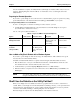
Chapter 3 Running DiagTools in the Graphical Mode (from Diskette) Before continuing, ensure that the following are correctly configured... Starting Configuration Detection Press the F2 function key to continue with DiagTools and start the Configuration Detection tests. You do not need to run the Setup utility. Table 3-1.
Chapter 3 Running DiagTools in the Graphical Mode (from Diskette) Interpreting Basic Test Results Once you run the DiagTools Basic Tests, you can see whether any component failed. For this, DiagTools reports whether the Basic System Test result is “passed” or “failed”. • If the Basic System Test result is “failed”, determine details of the problem as follows: 1. If the Basic System Test result was “failed”, check to see whether there is an error message in the Support Ticket.
Chapter 3 Running DiagTools in the Graphical Mode (from Diskette) Running the Advanced System Tests Advanced System Test Menus and Options The graphical interface of the Advanced System Tests displays a color screen and initializes the various tests. This may take a few minutes. The Advanced System Tests are listed across the top of the screen (and in the list shown below). Use the arrow keys to highlight the type of tests you want to run.
Chapter 3 Running DiagTools in the Graphical Mode (from Diskette) b. To select a series of tests, highlight the item to be tested on the Main Menu. Then press the F6 function key. Check marks appear next to all tests in the highlighted menu, indicating that those tests are selected. b. Press the F10 function key to start the a test or a series of tests. c.
Chapter 3 Running DiagTools in the Graphical Mode (from Diskette) About the Support Ticket The Support Ticket is a text file you can create using DiagTools. It lists the hardware detected and the test results.
Chapter 3 Running DiagTools in the Graphical Mode (from Diskette) down the NetServer, redo the installation, and replace all covers. Redo the system installation using the Setup utility on the HP NetServer Navigator CD-ROM. Then run DiagTools again to see whether all components are detected. • If (after reconfiguring the NetServer and booting up with DiagTools) all components are detected, then rerun the basic tests. See “Running the Basic Tests.
4 Running DiagTools in the Text Mode (from the Utility Partition) Preparation in Advance Once you have completed the steps in chapter 2 under “DiagTools Can Be Installed with the Utility Partition,” you can start the text-based mode by rebooting to the Utility Partition. NOTE After you boot up, you can get basic information on DiagTools and its latest release notes, by choosing 5. View DiagTools Readme.
Chapter 4 Running DiagTools in the Text Mode (from the Utility Partition) CAUTION Before you reboot the server be sure users have been warned and network operations shut down gracefully, if possible. 2. Reboot the NetServer and watch the console screen for the Utility Partition Prompt. When you see the prompt, press F12 to enter the Utility Partition. Confirm the command if requested. 3. Nine items are presented in the menu.
Chapter 4 Running DiagTools in the Text Mode (from the Utility Partition) and choose View Test Results. NOTE In the Misc Menu, only the Page Up and Page Down keys can be used to move up and down in text. Use the Esc key to exit back to the menu. Interpreting Basic Test Results If the Basic System Test result is “failed”, determine details of the problem as follows: a. Check to see whether there is an error message in the Support Ticket.
Chapter 4 Running DiagTools in the Text Mode (from the Utility Partition) the screen (and in the list shown below). Use the arrow keys to highlight the type of tests you want to run. System Memory IDE FDD (Flexible Disk Drive) SCSI KBD (Keyboard) Video Misc Batch A drop-down menu will display the available individual tests.
Chapter 4 Running DiagTools in the Text Mode (from the Utility Partition) IDE FDD (Flexible Disk Drive) SCSI KBD (Keyboard) Misc Batch NOTE Do NOT use the Erase Errors List command that appears briefly during test operation. It would erase the error list that you will use to create a Support Ticket. 3. To view all the test results use the Test Result Viewer in the Misc menu. To update Support Ticket with the results from the tests run, press Esc and choose 6. Return to Main Menu 3.
Chapter 4 Running DiagTools in the Text Mode (from the Utility Partition) Verify that DiagTools correctly detected all processors and memory on the system board (as listed in Table 4-2). Also verify DiagTools correctly detected all SCSI devices. If all processors, memory, and SCSI devices were detected, review the rest of the Support Ticket. (See “Reviewing Results” sections in this chapter.
Chapter 4 Running DiagTools in the Text Mode (from the Utility Partition) Each time you create a Support Ticket, it overwrites the previous one. To preserve a Support Ticket, copy its file elsewhere, rename it, or remove the diskette where it is located from the drive. You can view a Support Ticket with a text editor. You can also use the text editor to add your comments to the Support Ticket. Save Support Tickets you think contain important information for future reference.
Chapter 4 Running DiagTools in the Text Mode (from the Utility Partition) • If any processors, memory or SCSI devices (listed in Table 4-2) are still not detected, it is recommended that you run the Basic System Tests and create a Support Ticket anyway. Doing so may give more information to help diagnose what the problem is.
5 Error Message Reference Error Messages and Their Sources Errors are designated by a hexadecimal number. These numbers are listed in this chapter with a simple description of their meaning and some actions the user can take to try to isolate the source of the error. Brief descriptions of the tests which generate each type of error are listed within the error message table. Table 3-1.
Chapter 5 Code Error Message Reference Description Recommended Action execution error. 0007h Verify a Segment for Reading) instruction execution error. Make sure the CPU is seated properly or replace the CPU. 0008h VERW (Verify a Segment for Writing instruction execution error.) 1. Take ESD precautions and make sure the system board is seated. 2. Check the seating of the voltage regulator module (VRM) if present. 3. Be sure the processor board (if any) is seated. 4.
Chapter 5 Code Error Message Reference Description Recommended Action GS registers. 3. Be sure the processor board (if any) is seated. 4. Make sure the CPU chip is seated. 5. Make sure the memory elements (DIMMs) are properly seated. 6. Check system fans. If overheating occurs, chip may shut down. 7. If the system ran with temperature high, let it cool for 30 minutes, then restart. 8. If system repeatedly shows this error, replace the CPU chip or board, as appropriate.
Chapter 5 Error Message Reference Code Description Recommended Action 001Eh The detected CPU Speed is not the same as specified. Check jumpers or switches on the system board to be sure they are set properly according to the technical reference label or card. 0020h NDP not ready. 1. Take ESD precautions and make sure the system board is seated. 2. Check the seating of the voltage regulator module (VRM) if present. 3. Be sure the processor board (if any) is seated. 4.
Chapter 5 Code Error Message Reference Description Recommended Action 5. Make sure the memory elements (DIMMs) are properly seated. 6. Check system fans. If overheating occurs, chip may shut down. 7. If the system ran with temperature high, let it cool for 30 minutes, then restart. 8. If system repeatedly shows this error, replace the CPU chip or board, as appropriate. 0025h NDP control word read or write error. 1. Take ESD precautions and make sure the system board is seated. 2.
Chapter 5 Code Error Message Reference Description Recommended Action 3. Be sure the processor board (if any) is seated. 4. Make sure the CPU chip is seated. 5. Make sure the memory elements (DIMMs) are properly seated. 6. Check system fans. If overheating occurs, chip may shut down. 7. If the system ran with temperature high, let it cool for 30 minutes, then restart. 8. If system repeatedly shows this error, replace the CPU chip or board, as appropriate. 002Bh Integer load or store error. 1.
Chapter 5 Error Message Reference Code Description Recommended Action 0030h Read/Write test on DMA controller 1 failed. 1. Take ESD precautions and make sure the system board is seated. 2. Check the seating of the voltage regulator module (VRM) if present. 3. Be sure the processor board (if any) is seated. 4. Make sure the CPU chip is seated. 5. Make sure the memory elements (DIMMs) are properly seated. 6. Check system fans. If overheating occurs, chip may shut down. 7.
Chapter 5 Code Error Message Reference Description Recommended Action 8. If system repeatedly shows this error, replace the CPU chip or board, as appropriate. 0050h The Timer Periodic Interrupt is not being generated. 1. Take ESD precautions and make sure the system board is seated. 2. Check the seating of the voltage regulator module (VRM) if present. 3. Be sure the processor board (if any) is seated. 4. Make sure the CPU chip is seated. 5. Make sure the memory elements (DIMMs) are properly seated.
Chapter 5 Code Error Message Reference Description Recommended Action 6. Check system fans. If overheating occurs, chip may shut down. 7. If the system ran with temperature high, let it cool for 30 minutes, then restart. 8. If system repeatedly shows this error, replace the CPU chip or board, as appropriate. 0062h The Real Time Clock is running at a faster rate. 1. Take ESD precautions and make sure the system board is seated. 2. Check the seating of the voltage regulator module (VRM) if present. 3.
Chapter 5 Error Message Reference Code Description Recommended Action 0074h CMOS RAM time is invalid. Run BIOS Setup if problem persists replace battery, if present. Then replace the system board. 0075h Time-base frequency divider set at incorrect value. Reset the system and set BIOS Setup parameter. If the problem persists--replace CMOS RAM and the battery. 0076h DiagTools Error Download a new version of DiagTools from the HP web site and run it.
Chapter 5 Code Error Message Reference Description Recommended Action 5. Make sure the CPU chip is seated. (Take ESD precautions.) 6. Make sure the memory elements (DIMMs) are properly seated. 7. Check system fans. If overheating occurs, chip may shut down. 8. If the system ran with temperature high, let it cool for 30 minutes, then restart. 9. If system repeatedly shows this error, replace PCI Card and system board. 0084h Cannot access PCI devices through the FIND_PCI_DEVICE call. 1.
Chapter 5 Code Error Message Reference Description Recommended Action 8. If the system ran with temperature high, let it cool for 30 minutes, then restart. 9. If system repeatedly shows this error, replace PCI Card and system board. 0088h BIOS32 service directory integrity check failed. Update the System BIOS. 0089h PCI bus transfer using standard PCI cycles failed. 1. Remove all unnecessary PCI cards and try the test again. If it still fails, make sure all PCI connectors are seated. 2.
Chapter 5 Code Error Message Reference Description Recommended Action twice. 0097h DiagTools Error Download a new version of DiagTools from the HP web site and run it. If you get the same error, call the HP Customer Care Center. 0098h DiagTools Error Download a new version of DiagTools from the HP web site and run it. If you get the same error, call the HP Customer Care Center. 0099h DiagTools Error Download a new version of DiagTools from the HP web site and run it.
Chapter 5 Code Error Message Reference Description Recommended Action 2. If necessary, update the BIOS. 3. Clear the CMOS and rerun configuration. See directions on the technical reference label or card. 4. Make sure the system board is seated. 5. Check the seating of the voltage regulator module (VRM) if present. 6. Be sure the processor board (if any) is seated. 7. Make sure the CPU chip is seated. (Take ESD precautions.) 8. Make sure the memory elements (DIMMs) are properly seated. 9.
Chapter 5 Code Error Message Reference Description Recommended Action 6. Be sure the processor board (if any) is seated. 7. Make sure the CPU chip is seated. (Take ESD precautions.) 8. Make sure the memory elements (DIMMs) are properly seated. 9. Check system fans. If overheating occurs, chip may shut down. 10. If the system ran with temperature high, let it cool for 30 minutes, then restart. 11. If system repeatedly shows this error, replace the element with the CMOS.
Chapter 5 Code Error Message Reference Description Recommended Action restart. 11. If system repeatedly shows this error, replace the element with the CMOS. 00A7h NVRAM test failed. 1. Run the BIOS Setup program and reconfigure all settings. 2. If necessary, update the BIOS. 3. Clear the CMOS and rerun configuration. See directions on the technical reference label or card. 4. Make sure the system board is seated. 5. Check the seating of the voltage regulator module (VRM) if present. 6.
Chapter 5 Code Error Message Reference Description Recommended Action reference label or card. 4. Make sure the system board is seated. 5. Check the seating of the voltage regulator module (VRM) if present. 6. Be sure the processor board (if any) is seated. 7. Make sure the CPU chip is seated. (Take ESD precautions.) 8. Make sure the memory elements (DIMMs) are properly seated. 9. Check system fans. If overheating occurs, chip may shut down. 10.
Chapter 5 Code Error Message Reference Description Recommended Action 6. Check system fans. If overheating occurs, chip may shut down. 7. If the system ran with temperature high, let it cool for 30 minutes, then restart. 8. If system repeatedly shows this error, replace the CPU chip or board, as appropriate. 00C5h Saturation Arithmetic test failed. 1. Take ESD precautions and make sure the system board is seated. 2. Check the seating of the voltage regulator module (VRM) if present. 3.
Chapter 5 Code Error Message Reference Description Recommended Action 4. Make sure the CPU chip is seated. 5. Make sure the memory elements (DIMMs) are properly seated. 6. Check system fans. If overheating occurs, chip may shut down. 7. If the system ran with temperature high, let it cool for 30 minutes, then restart. 8. If system repeatedly shows this error, replace the CPU chip or board, as appropriate. 00CAh Exit MMX state instruction(EMMS) failed. 1.
Chapter 5 Error Message Reference Code Description Recommended Action 0100h ROM read error. 1. Take ESD precautions and make sure the system board is seated. 2. Check the seating of the voltage regulator module (VRM) if present. 3. Be sure the processor board (if any) is seated. 4. Make sure the CPU chip is seated. 5. Make sure the memory elements (DIMMs) are properly seated. 6. Check system fans. If overheating occurs, chip may shut down. 7.
Chapter 5 Code Error Message Reference Description Recommended Action technical reference label or card. 5. Examine the support ticket and check for failures. 6. Bring the system down to its minimum memory configuration and rerun the test. 7. Build up the system by halves until the failure is located. 0135h ECC Correctable Error in DIMM socket YYYY. 1. Visually inspect the memory board to ensure proper seating. 2. Check to see all DIMMs are the correct HP part number. 3.
Chapter 5 Code Error Message Reference Description Recommended Action technical reference label or card. 5. Examine the support ticket and check for failures. 6. Bring the system down to its minimum memory configuration and rerun the test. 7. Build up the system by halves until the failure is located. 0160h There is an address short between bit xxh and yyh. 1. Visually inspect the memory board to ensure proper seating. 2. Check to see all DIMMs are the correct HP part number. 3.
Chapter 5 Code Error Message Reference Description Recommended Action 4. Check the positions of DIMMs to see that positioning matches that on the technical reference label or card. 5. Examine the support ticket and check for failures. 6. Bring the system down to its minimum memory configuration and rerun the test. 7. Build up the system by halves until the failure is located. 8. Change the memory board. 9. Change the system board. 10. Change the board where the DIMMs are located.
Chapter 5 Code Error Message Reference Description Recommended Action 5. Examine the support ticket and check for failures. 6. Bring the system down to its minimum memory configuration and rerun the test. 7. Build up the system by halves until the failure is located. 01A0h The pattern written at address XXXXXXXXh was qqqqh The pattern read back from that address was pppph. 1. Visually inspect the memory board to ensure proper seating. 2. Check to see all DIMMs are the correct HP part number. 3.
Chapter 5 Error Message Reference FDD (Flexible Disk Drive or Floppy) Tests Flexible Disk Drives are tested for rotational speed, elevator, and seek channel. Code Description Recommended Action 0301h Undefined or invalid command. 1. Try a different diskette. 2. Check the cable between the floppy drive and the system board. 3. Change the floppy drive. 4. Change the system board. 0302h DiagTools Error Download a new version of DiagTools from the HP web site and run it.
Chapter 5 Error Message Reference Code Description Recommended Action 0322h Floppy Speed Error. 1. Try a different diskette. 2. Check the cable between the floppy drive and the system board. 3. Change the floppy drive. 4. Change the system board. 0340h Seek operation failed. 1. Try a different diskette. 2. Check the cable between the floppy drive and the system board. 3. Change the floppy drive. 4. Change the system board. 0341h Undefined or invalid command in Random Test. 1.
Chapter 5 Code Error Message Reference Description Recommended Action Test. 3. Change the floppy drive. 4. Change the system board. 03FEh Diskette data read/write error in Sequential Test. 1. Try a different diskette. 2. Check the cable between the floppy drive and the system board. 3. Change the floppy drive. 4. Change the system board. 0380h Drive not ready. 1. Try a different diskette. 2. Check the cable between the floppy drive and the system board. 3. Change the floppy drive. 4.
Chapter 5 Code Error Message Reference Description Recommended Action 2. Replace the keyboard and rerun the test. 3. Replace the system board. 0413h Keyboard data stuck low/high. 1. Power down the system. (Caution, keyboards are not hot-swappable. A keyboard swap with power on may damage the system board.) 2. Replace the keyboard and rerun the test. 3. Replace the system board.
Chapter 5 Code Error Message Reference Description Recommended Action 4. Check for proper termination, using technical reference card or label. 5. Check system fans 6. Check firmware version of drive and update if necessary. 7. Replace the drive 8. Change the card or board that has the drive’s controller. 0502h SCSI device read error. 1. Check cables and connections: a) to SCSI components, b) to power source, c) between cards and backplane. 2. Inspect SCSI pins to ensure none are bent. 3.
Chapter 5 Code Error Message Reference Description Recommended Action 4. Check for proper termination, using technical reference card or label. 5. Check system fans 6. Check firmware version of drive and update if necessary. 7. Replace the drive 8. Change the card or board that has the drive’s controller. 0509h DiagTools Error Download a new version of DiagTools from the HP web site and run it. If you get the same error, call the HP Customer Care Center.
Chapter 5 Error Message Reference Code Description Recommended Action 0514h DiagTools Error Download a new version of DiagTools from the HP web site and run it. If you get the same error, call the HP Customer Care Center. 0515h Tape Selftest error. 1. Use a cleaning cartridge to make sure heads are clean. get the same error, call the HP Customer Care Center. 2. Replace the tape. 3. Check cables and connections: a) to SCSI components, b) to power source, c) between cards and backplane. 4.
Chapter 5 Code Error Message Reference Description Recommended Action 4. Check seating of board or SCSI card. 5. Check for proper termination, using technical reference card or label. 6. Check system fans 7. Check firmware version of drive and update if necessary. 8. Replace the drive 9. Change the card or board that has the drive’s controller. 0523h DiagTools Error Download a new version of DiagTools from the HP web site and run it. If you get the same error, call the HP Customer Care Center.
Chapter 5 Code Error Message Reference Description Recommended Action 4. Check seating of board or SCSI card. 5. Check for proper termination, using technical reference card or label. 6. Check system fans 7. Check firmware version of drive and update if necessary. 8. Replace the drive 9. Change the card or board that has the drive’s controller. 0528h DiagTools Error Download a new version of DiagTools from the HP web site and run it. If you get the same error, call the HP Customer Care Center.
Chapter 5 Error Message Reference Code Description Recommended Action 0606h DiagTools Error Report error to HP Customer Care Center and get the latest version of DiagTools. 0607h DiagTools Error Report error to HP Customer Care Center and get the latest version of DiagTools. 0608h FIFO register test failed at port XXXXh. Possible system board failure. 0609h FIFO trigger level test failed at port XXXXh. Possible system board failure.
Chapter 5 Error Message Reference Code Description Recommended Action 0803h DiagTools Error Report error to HP Customer Care Center and get the latest version of DiagTools. 0804h DiagTools Error Report error to HP Customer Care Center and get the latest version of DiagTools. 0805h DiagTools Error Report error to HP Customer Care Center and get the latest version of DiagTools. 0806h DiagTools Error Report error to HP Customer Care Center and get the latest version of DiagTools.
Chapter 5 Code Error Message Reference Description Recommended Action Drive x in Sector y. 2. Check the cable between the CD and its controller. 3. Change the CD drive. 4. Change the board where the controller for the CD drive is located. 0A06h Random data test failed. No CD in drive. 1. Insert a data CD in the drive. 2. Check the cable between the CD and its controller. 3. Change the CD drive. 4. Change the board where the controller for the CD drive is located.
Chapter 5 Code Error Message Reference Description Recommended Action 4. Be sure the processor board (if any) is seated. 5. Make sure the CPU chip is seated. (Take ESD precautions.) 6. Make sure the memory elements (DIMMs) are properly seated. 7. Check system fans. If overheating occurs, chip may shut down. 8. If the system ran with temperature high, let it cool for 30 minutes, then restart. 9. If system repeatedly shows this error, replace the CPU chip or board, as appropriate.
Chapter 5 Code Error Message Reference Description Recommended Action 4. Be sure the processor board (if any) is seated. 5. Make sure the CPU chip is seated. (Take ESD precautions.) 6. Make sure the memory elements (DIMMs) are properly seated. 7. Check system fans. If overheating occurs, chip may shut down. 8. If the system ran with temperature high, let it cool for 30 minutes, then restart. 9. If system repeatedly shows this error, replace the CPU chip or board, as appropriate.
Chapter 5 Code Error Message Reference Description Recommended Action 4. Be sure the processor board (if any) is seated. 5. Make sure the CPU chip is seated. (Take ESD precautions.) 6. Make sure the memory elements (DIMMs) are properly seated. 7. Check system fans. If overheating occurs, chip may shut down. 8. If the system ran with temperature high, let it cool for 30 minutes, then restart. 9. If system repeatedly shows this error, replace the CPU chip or board, as appropriate.
Chapter 5 Code Error Message Reference Description Recommended Action 4. Be sure the processor board (if any) is seated. 5. Make sure the CPU chip is seated. (Take ESD precautions.) 6. Make sure the memory elements (DIMMs) are properly seated. 7. Check system fans. If overheating occurs, chip may shut down. 8. If the system ran with temperature high, let it cool for 30 minutes, then restart. 9. If system repeatedly shows this error, replace the CPU chip or board, as appropriate.
Chapter 5 Code Error Message Reference Description Recommended Action Failure. The pattern read back from the cache is not same as the pattern written. label or card. 2. Make sure the system board is seated. 3. Check the seating of the voltage regulator module (VRM) if present. 4. Be sure the processor board (if any) is seated. 5. Make sure the CPU chip is seated. (Take ESD precautions.) 6. Make sure the memory elements (DIMMs) are properly seated. 7. Check system fans.
Chapter 5 Code Error Message Reference Description Recommended Action 9. If system repeatedly shows this error, replace the CPU chip or board, as appropriate. 1031h Multi Processor Failure. L2 Cache Parity error 1. Reduce the system to its minimum configuration per the technical reference label or card. 2. Make sure the system board is seated. 3. Check the seating of the voltage regulator module (VRM) if present. 4. Be sure the processor board (if any) is seated. 5. Make sure the CPU chip is seated.
Chapter 5 Code Error Message Reference Description Recommended Action 7. Check system fans. If overheating occurs, chip may shut down. 8. If the system ran with temperature high, let it cool for 30 minutes, then restart. 9. If system repeatedly shows this error, replace the CPU chip or board, as appropriate. 1201h DiagTools Error Download a new version of DiagTools from the HP web site and run it. If you get the same error, call the HP Customer Care Center.
A Test Menus Basic Test Menus NOTE DiagTools will run a different selection basic tests depending upon the type of hardware components present.
Appendix A Test Menus Advanced System Tests You may select Advanced System Tests by pressing F2 after completion of Basic Tests When advanced tests are run, the following menus are available: Advanced System Test Menus System Memory IDE FDD (Flexible Disk Drive) SCSI KBD (Keyboard) Video Misc (Miscellaneous) Batch 70
B Test Descriptions Test Descriptions System Test Menu The tests included in the System Test Menu exercise the basic functionality of the CPU, ensuring that the registers, the flags, and both the basic and protected instructions work as expected. It includes tests of the chip speed as well as the operation of integrated controllers for coprocessing, DMA, interrupts, and the timers and clock functionality. Specialized tests for PCI devices, Plug and Play devices, and MMX instructions are also included.
Appendix B Test Descriptions Timer Test This test checks the accuracy of the timer count by calibrating it against the periodic interrupt of the real time clock (RTC). Real Time Clock Test This test checks the accuracy of the real time clock by calibrating it against the system timer. It also does a pattern test on RTC. CMOS Validity Test This test checks the condition of AT CMOS RAM (non-volatile memory).
Appendix B Test Descriptions Memory Test Menu The Memory Test Menu includes tests that exercise all aspects of the storage media and key memory locations of the system. The functionality of the boot ROM, parity over the whole memory space, patterns, addressing, refresh functions, and the data bus have specific tests included in the menu. Specialized testing for memory caching, performance, and the proprietary Pentium II L2 Cache are included.
Appendix B Test Descriptions Address Test The address test writes a value in one location of memory and then scans the entire memory to find out a reflection of that value. Refresh Test This test makes sure the refresh circuitry is functioning and measures the refresh interval. An error is reported if this interval is not within +/- 5 percent of the standard refresh interval of 15 microseconds. Data Bus Test This test will check the data bus for a short.
Appendix B Test Descriptions Elevator seek Test This test verifies the track-to-track seeking capability of the floppy drive. This test is sometimes called a butterfly test. Disk Change Line Test This test verifies the change line capability of the floppy drive. KBD (Keyboard) Tests The KBD Test Menu includes testing the keyboard controller, scanning, LEDs, clock line, and data line for proper functionality.
Appendix B Test Descriptions SCSI Disk Read Test This test reads logical blocks from the SCSI disk. If the starting logical block number and end logical block number fields are not specified, the test starts reading from block 0 and terminates at the last block of the disk. SCSI Tape Unit Tests SCSI Tape Buffer Test This test writes data, reads back and compares with the data written to the internal buffer on the SCSI Tape Unit. The media is not accessed so data remains unaffected.
Appendix B Test Descriptions Serial Port A maximum of four serial ports (COM1 through COM4) are tested. All parameters i.e. number of data bits, number of stop bits, parity type etc. can be individually selected for each port. The tests that are performed on the serial ports include: Register test, Interrupt ID test, Internal loopback test, Line status test, Modem control register test, Data transfer test (at baud rates from 300 BPS to 115.2KBPS and FIFO test.
C Batch Menu Batch Menu The Batch Menu allows users to specify what tests to run as well as how many times to repeat a particular test. Edit Batch Parameters Selecting this option is the same as pressing from the main menu. This option allows you to specify different groups of parameters: Parameters for all tests, Repeat Counts, and Batch mode parameters. Repeat count applies to the count each test will be run on a per pass bases.
Appendix C Batch Menu Run Batch Selecting this options is the same as pressing from the main menu. This option allows you to run all of the selected tests in batch mode. Batch Help This option will display detailed messages on batch function.
Index A Advanced System Tests menus, 70 Advanced System Tests, DiagTools, 11 B Basic System Test, Diag Tools, 10 basic tests memory, 69 miscellaneous, 69 SCSI, 69 system, 69 what is included, 69 C capability of DiagTools, 2 D diagnostic tools purpose, 1 DiagTools flexible diskette, 9 problems, 9 when to use, 5 Diskette How to Make a Boot Diskette, 6 Rebooting with DiagTools, 9 E Error Code Viewer, DiagTools, 14, 23 error messages Categories, 25 description of format, 3 flexible disk or floppy, 49 keyboard,