Microsoft Cluster Installation Documentation To assist you in installing your HP NetServer Microsoft Cluster, this file contains three separate documents combined into one pdf file. • Configuration Guide - This guide provides configuration information specific to your cluster configuration that you will need during the installation of your cluster. • HP NetServer Microsoft Cluster Installation Guide - Use this document to install the cluster.
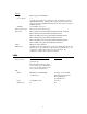
Version History 18 November 1998 Revised the Configuration Guide to add, “6 maximum per NetRAID adapter” to Logical Disks in Shared Storage. 15 September 1998 Revised the Configuration Guide to add, “Logical Disks – 1 per RAID array” to Shared Storage.
HP NetServer LH Pro with NetRAID (HP Storage System/6) Cluster Configuration Guide 17 November 1998 Introduction This document defines the supported HP NetServer LH Pro configurations for Microsoft Cluster Server. These configurations minimize single points of failure, provide maximum availability, and have been certified by Hewlett-Packard and Microsoft. This guide is prescriptive; it describes the HP NetServer LH Pro configurations supported by HP.
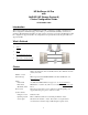
SPU Model Clock speed No. of CPUs BIOS version CPU cache RAM No. of power supplies Hot swap cages Local storage I/O slots: HP NetServer LH Pro 6/200 Model 1 200 MHz 2 (at least two are required) 4.05.14 PF or later Any size 128 MB minimum. Must be HP. 2 May use for local storage; but not use for shared storage. Internal or external, using any controller. Must use HP disks. See Local Storage below. P9 - Shared storage controller (P8 if using NetRAID for local storage.
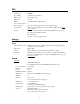
Cabinet Model No. of cabinets SCSI IDs SPU hot swap cages Disk drives: Cables RAID arrays HP Storage System/6 D3604B 1, 2 A cluster with a single storage cabinet has only one SCSI bus connected to HP NetRAID channel 0. A cluster with 2 storage cabinets must have one cabinet connected to NetRAID channel 0 and the other cabinet connected to NetRAID channel 1. Any SCSI IDs except 6 or 7 May not be used for shared storage. HP 2.1 GB Hot-Swap Ultra SCSI Disk Module D3582B or D3582C HP 4.
This page intentionally left blank.
HP NetServer LH Pro Microsoft Cluster Installation Guide 1 October 1997
Notice The information contained in this document is subject to change without notice. Hewlett-Packard makes no warranty of any kind with regard to this material, including, but not limited to, the implied warranties of merchantability and fitness for a particular purpose. Hewlett-Packard shall not be liable for errors contained herein or for incidental or consequential damages in connection with the furnishing, performance, or use of this material.
Table of Contents Overview of an HP NetServer LH Pro Cluster Installation............................................... 1 Part 1: Installing Additional Hardware Components ........................................................ 5 Part 2: Setting Up the HP Storage System/6 .................................................................. 9 Part 3: Configuring the HP NetRAID Adapter................................................................
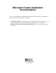
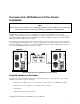
Overview of an HP NetServer LH Pro Cluster Installation NOTE Hewlett-Packard does not support nor recommend the installation of clustered HP NetServer systems using Microsoft Cluster Server software unless installed by an HP Cluster Certified Installer. An HP NetServer LH Pro cluster provides a reliable low-cost, increased-availability solution for critical applications. The basic cluster consists of two HP NetServer LH Pro systems coupled to one (or two) HP Storage System/6 using HP NetRAID adapters.
Overview of an HP NetServer LH Pro Cluster Installation Unless otherwise specified, when more than one component is required, the additional component(s) must be identical in manufacture and configuration. Hardware The following hardware components are required for HP NetServer LH Pro cluster installations.
Overview of an HP NetServer LH Pro Cluster Installation Software To set up an HP NetServer LH Pro running Microsoft Cluster Server, use the Microsoft Windows NT Server (Enterprise Edition), version 4.0, which includes the following: • Windows NT, version 4.0 • Windows NT Service Pack 3 • Microsoft Cluster Server installation software The following HP software products are also required: • HP NetServer Navigator CD-ROM, version G.00.
Overview of an HP NetServer LH Pro Cluster Installation Setup Procedure You begin a cluster installation by setting up the hardware at both HP NetServer LH Pros, referred to here as System A and System B. The installation is complete when you have setup and tested the Microsoft Cluster Server software on both systems. A Microsoft Cluster Server based on HP NetServers is assembled in six major parts: • Part 1. Install Additional Hardware components • Part 2. Setup the Storage System/6 • Part 3.
Part 1: Installing Additional Hardware Components When HP NetServer LH Pros are shipped from the factory, they are configured for stand-alone operation. The first step in creating a cluster is to reconfigure the two HP NetServers for use in a cluster. Because these steps involve opening the HP NetServers, HP recommends you use a Portable Field Service Grounding Kit (3M part number 8505, or equivalent). The kit contains a wrist strap, anti-static mat, and cable.
Part 1: Installing Additional Hardware Components Installing Peripheral Components In this step, you will install peripheral components that are necessary for the servers to operate in a cluster configuration. NOTE The standard HP NetServer LH Pro is equipped with 32 to 64 MB of memory. Cluster operations require a minimum of 128 MB of memory.
Part 1: Installing Additional Hardware Components 4. Connect the free end of the C11 cable from the CD-ROM drive to the 50- pin output connector on the top hot swap cage. The output connector is on the left when the cage is viewed from the back. 5. Remove the C23 cable from the SCSI B controller connector and coil the cable up out of the way. 6. Remove the C22 cable from channel 0 of the NetRAID card and connect it to SCSI B. 7. Set the DIP switches on the back of the hot swap cages as shown below.
Part 1: Installing Additional Hardware Components The connector is keyed to insure correct connection. When connected, the battery backup module protects the HP NetRAID Adapter’s cache memory. HP NetRAID Adapter with Connected Battery Pack NOTE To assemble a certified Microsoft Cluster Server, use only an HP NetRAID Adapter (model number D4943A). 2. Using a TorxTM driver, remove the PCI card holdown plate. 3. With the battery backup module connected, install the HP NetRAID Adapter in PCI slot 9. 4.
Part 2: Setting Up the HP Storage System/6 In this section, you prepare the HP Storage System/6 for cluster operations by: • Configuring the internal cabling on the HP Storage System/6 • Assigning SCSI IDs (via dip switches) for the disks in the HP Storage System/6 Verifying SS6 Internal Cabling Before connecting the disks housed in the HP Storage System/6, you need to setup the Storage System/6’s internal cables to support the cluster.
Part 2: Setting Up the HP Storage System/6 4. Swing the door open, as shown in Step 2. 5. Lift the door off the chassis. Repeat Steps 1-5 for each Storage System/6 to be included in the cluster. HP Storage System/6 Internal Cabling Using the schematic view of the HP Storage System/6’s internal cabling shown below, you need to check and, if necessary re-route, the three cables located inside the storage unit.
Part 2: Setting Up the HP Storage System/6 Assigning SCSI IDs To configure the shared disks, you need to change the SCSI ID assignments for each of the HP Storage System/6 units you are including in the cluster: 1. Check, and if necessary re-assign, SCSI ID’s for both the upper and lower cages. Configure the DIP switches as indicated in the figure below. Note that the upper cage settings are shown in their default positions.
Part 3: Configuring the HP NetRAID Adapter In Parts 1 and 2, you installed additional hardware in your HP NetServers to support cluster operations, and configured both the HP NetServers and the shared storage units for use in the cluster. In Part 3, you will be configuring the HP NetRAID Adapters you installed in Systems A and B using the HP NetRAID Express Tool. To configure the HP NetRAID Adapter, at both Systems A and B: 1. Ensure that Systems A and B are not cabled to the shared storage cabinets.
Part 3: Configuring the HP NetRAID Adapter 9. If the previous step did not force a reboot, continue pressing Escape to exit the NetRAID Express Tools utility. When prompted to exit, press Yes. The utility re-boots to enable the changes you have made. When the HP NetRAID Adapters on both systems are configured, proceed to "Part 4: Installing Microsoft Windows NT, and configuring the LAN Adapters.
Part 4: Installing Microsoft Windows NT and Configuring the LAN Adapters After you have configured the HP NetRAID Adapter, you are ready to install Microsoft Windows NT Server, Enterprise Edition. Prior to Windows NT installation, use the HP EISA Configuration Utility to configure the hardware for use with the network operating system. NOTE Ensure that your HP NetServer Navigator CD-ROM is designated "version G.00.85", or later before continuing with the HP EISA Configuration Utility.
Part 4: Installing Microsoft Windows NT and Configuring the LAN Adapters Installing Microsoft Windows NT In addition to installing Microsoft Windows NT, in this section you also configure the operating system for cluster operations. To install Microsoft Windows NT for Microsoft Cluster Server operations, at both Systems A and B: 1. Insert the Base CD of the Microsoft Windows NT Server, Enterprise Edition and reboot the system. Microsoft Windows NT begins installation. 2.
Part 5: Installing HP NetRAID Software and Configuring the Disk Arrays After Windows NT has been installed and configured for cluster operations and you have upgraded the operating system with Service Pack 3, you need perform the following tasks to prepare Systems A and B for the Microsoft Cluster Server software: • Install the NT NetRAID driver • Install NetRAID Assistant software • Connect the shared storage • Configure the disk arrays.
Part 5: Installing HP NetRAID Software and Configuring the Disk Arrays Connecting the Cluster’s Shared Storage Refer to one of the following schematics as you connect the HP Storage System/6 cabinet(s) to the cluster’s NetServers. Use only D5957A NetRAID Cluster Adapters to connect the HP Storage System/6 to the servers. To connect the HP Storage System/6 unit(s) to the HP NetServers: 1. Power down all cluster hardware including both HP NetServers and the HP Storage System/6 cabinet(s) 2.
Part 5: Installing HP NetRAID Software and Configuring the Disk Arrays System A System B SCSI-B SCSI-A #1 #0 SCSI-B SCSI-A SYSTEM DISK CD-ROM External SS/6 External SS/6 SYSTEM DISK CD-ROM NetRAID NetRAID Ch0 Ch1 A B A B Ch0 Ch1 HP NetServer LH Pro Cluster with Two HP Storage System/6 Units NOTE NetRAID channels must not cross. Connect HP NetRAID channel 0 leading from both HP NetServers to the same external storage cabinet.
Part 5: Installing HP NetRAID Software and Configuring the Disk Arrays The front panel of the storage system includes two-digit, seven-segment LEDs. Because the LEDs are powered by the internal power supply, if the power supply is not functioning you will not see a display. When operations are normal, the display shows "HP" or the unit identification number.
Part 5: Installing HP NetRAID Software and Configuring the Disk Arrays To set up your RAID arrays: 1. Review the examples and procedures included in Appendix C before using HP NetRAID Assistant. 2. Follow the procedures outlined in Appendix C for the RAID level appropriate to your installation. Refer to the HP NetRAID User Guide in HP Information Assistant for detailed information about HP NetRAID configuration.
Part 5: Installing HP NetRAID Software and Configuring the Disk Arrays Disk Administrator lists disks in order, beginning with local (non-shared) disks first. If you have three local disks, Disk Administrator will designate them Disk 0, Disk 1, and Disk 2. The shared arrays (logical disks) will be identified as Disk 3, Disk 4, and so on. Next, using Disk Administrator, you will create a single partition on each of the logical disks you just configured. To create a partition for each array: 1.
Part 5: Installing HP NetRAID Software and Configuring the Disk Arrays 3. In the Assign Drive Letter dialog box, select a drive letter. To avoid confusion later on choose sequential drive letters. 4. From the NT Disk Administrator’s Tools menu, choose Format and, in the space provided, provide a Volume Label for the drive. Choosing a descriptive label such as "Shared Drive F" will be helpful later when you need to match drive letter assignments at System B. Disk Administrator, Formatting a Disk 5.
Part 5: Installing HP NetRAID Software and Configuring the Disk Arrays Confirming the Arrays on System B To confirm the cluster’s disk configuration, you need to check System B to be sure it recognizes all the drives you created to System A. 1. Boot System B. You may, while booting System B, get the message "Configuration of NVRAM and drives mismatch" in the NetRAID boot banner.
Part 5: Installing HP NetRAID Software and Configuring the Disk Arrays Disk Administrator, Mismatched Drive Letters 2. Click on a disk box to select one of the disks that includes an array to be shared by the cluster. Disk Administrator highlights the selected disk. 3. Select Tools from the pull-down menu, and choose Assign Drive Letter. 4. Based on the Volume Labels you assigned the arrays ("Shared F" in the above example), assign a drive letter that matches the System A drive letter assignment.
Part 6: Installing and Testing Microsoft Cluster Server Software During installation at System B, you will create a Microsoft Cluster Server. Initially, it is a cluster with only one server, System B. Later, you will join System A to the cluster and thus create a standard two-server cluster. If you need more information about the installation process outlined here, see the Microsoft® Windows NT™ Cluster Server Administrator's Guide.
Part 6: Installing and Testing Microsoft Cluster Server Software Microsoft Cluster Administrator, Assigning a Cluster Name 4. Enter a name for the cluster. Make note of the name you enter here. You will need to provide the identical name during Microsoft Cluster Server software setup at System A. Click Next. 5. Setup allows you to specify a directory in which to install the cluster files. Select a directory and click Next. 6. Setup requires a domain account to run MSCS in.
Part 6: Installing and Testing Microsoft Cluster Server Software 10. Configure your network resources (LAN adapters). Setup presents a dialog box for each LAN adapter installed in your HP NetServer. The intra-cluster LAN is shown first with the Adapter Name and IP address already filled in (setup supplies the IP address that you specified during NT installation). Enter a network name for the resource and check Enable for Cluster Use. Identify the resource according to use (e.g. cluster LAN 1).
Part 6: Installing and Testing Microsoft Cluster Server Software NOTE If you previously defined Systems A and B as residing on different subnets, the client LAN will be unable to assume responsibility for intra-cluster (heartbeat) communication. 13. Setup prompts you for the Cluster IP address. Input the proper IP address and subnet mask for the CLUSTER. Note that what is required here is an IP address for the cluster. Do not enter either of the IP addresses assigned to System A or System B. 14.
Part 6: Installing and Testing Microsoft Cluster Server Software Testing the Cluster Installation The installation of an HP NetServer cluster is checked by running two tests. The Microsoft Cluster Administrator Sanity test is run, then the HP Cluster Installation Test is run. The Microsoft Cluster Administrator Sanity test is run on a node of the cluster and uses the cluster administrator to perform some basic cluster tests.
Part 6: Installing and Testing Microsoft Cluster Server Software On each cluster node enable the local disk for sharing. In Windows NT Explorer, right click the local drive, then select Properties | Sharing | Share As | OK. Setting up Two File Shares (use the example below). NOTE When setting up file shares, names must be assigned to resources. The example below uses default names and names that are typically assigned when running this test.
Part 6: Installing and Testing Microsoft Cluster Server Software 6. On the TCP/IP Address Parameters dialog enter the following, then click Next. : • Address. Use the IP address you have allocated for this file share. • Subnet Mask. Type in the associated subnet mask for this IP address, then click Finish. Setting Up a Network Name Resource 1. Right click the Disk Group and select New | Resource. On the New Resources dialog complete the following fields, then click Next: • Resource Type.
Part 6: Installing and Testing Microsoft Cluster Server Software 4. On the Disk Parameters dialog complete the following, then click Finish: • Name. Type the desired name (e.g., "Disk_U"). • Path. Type "C:\" • Comment. Nothing needs to be entered here. • User Limit. Check Maximum Allowed. Bring Resources Online The file share for this disk group is now complete. To bring the disk share online, right click the Disk Group and select Bring Online.
APPENDIX A Obtaining HP NetRAID Utilities To get updated versions of the HP NetRAID utilities that contain firmware, driver and the HP NetRAID Assistant program, you must download, extract, and then copy of nr_clust.exe, a special version of the HP NetRAID utilities for cluster installations. To obtain NetRAID firmware, you need to download nr_clust.exe from the HP’s FTP site. [Enter FTP site address here] Once you have downloaded nr_clust.
APPENDIX B Updating HP NetRAID Firmware After you created your NetRAID utilities diskettes (see Appendix A), use the flash utility diskette labeled NetRAID Firmware & Driver to upgrade the adapter firmware on both systems. To flash the NetRAID adapter firmware: 1. Shut down the system and boot to DOS, 2. Insert the flash utility diskette, NR Firmware & Driver, in the system’s floppy drive. 3. At the A: prompt, run the firmware update program mflash.
APPENDIX C RAID Array Configuration The following two examples illustrate the RAID array configuration process for HP NetServer Clusters: • Setting up RAID 1 arrays on an HP NetServer cluster • Setting up RAID 5 arrays on an HP NetServer cluster After you have finished defining and configuring the cluster’s arrays using HP NetRAID Assistant, you will need to return to Part 5 and finish array configuration using the Windows NT Disk Administrator utility.
Appendix C RAID Array Configuration From the Windows NT System A Start menu, click Programs | NetRAID | NetRAID Assistant. The HP NetRAID Assistant program loads and displays its main window. HP NetRAID Assistant Screen As you can see on the NetRAID Assistant screen, HP NetRAID Assistant lists the Physical Devices (actual physical drives) and Logical Devices (RAID arrays). The Physical Devices pane lists the drives in columns by channel.
Appendix C RAID Array Configuration Refer to the HP NetRAID User Guide in Information Assistant for more information about HP NetRAID Assistant. Setting Up the Arrays To set up an array you need to define an array, set its parameters, and then initialize the array. Define an Array RAID arrays are defined using the Configuration Wizard. To define a RAID 1 array: 1. On the NetRAID Assistant’s menu bar click Configuration, then Wizard. 2. Select Custom in the dialog box and click Next.
Appendix C RAID Array Configuration 1. Click Next. The Configuration Wizard displays its Logical Drive Definition window. 2. The Logical Drive Definition window shows the array’s RAID level (RAID 1) and its usable size. Notice that the size of the array is one half of the sum of the capacity of the two drives composing the array, since all data is duplicated. 3. Click Advanced and verify that Write Policy is set to "Write Thru" and then click OK. 4. Click Accept to set the array parameters. 5.
Appendix C RAID Array Configuration 2 Block 2.1 Parity 2 Block 2.2 3 Parity 3 Block 3.1 Block 3.2 The preceding table shows how data is distributed for RAID 5. As you can see, each stripe has one block assigned to track parity data. Parity data can be used to reconstruct the data on that stripe if one of the disks should fail. RAID 5 distributes parity information equally among all disk drives to equalize data I/O and achieve better overall performance.
Appendix C RAID Array Configuration 3. In the Array Definition window define an array by selecting the three physical drives in the Physical Devices pane that will compose the array. As you click your selections, they are highlighted in the Physical Devices pane. 4. Click Add to Array, then Accept Array. Set Array Parameters After the array has been defined, its parameters must be set. 1. Click Next. The Configuration Wizard displays its Logical Drive Definition window. 2.