HP NetServer LXr 8000 and LXr 8500 Installation Guide for Compaq® 4000/7000 Racks HP Part Number 5967-6670 Printed in September 1999
Notice The information contained in this document is subject to change without notice. Hewlett-Packard makes no warranty of any kind with regard to this material, including, but not limited to, the implied warranties of merchantability and fitness for a particular purpose. Hewlett-Packard shall not be liable for errors contained herein or for incidental or consequential damages in connection with the furnishing, performance, or use of this material.
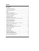
Contents About This Guide ................................................................................................. 1 1 Introduction...................................................................................................... 3 Compaq Rack-Optimized Kit ............................................................................. 3 Order of Installation Operations......................................................................... 4 Compaq Rack Precautions..............................
Contents Install the Nameplate....................................................................................... 38 Install the Compaq Rack Front Bezel.............................................................. 40 A Warranty and Support................................................................................... 41 Hardware Accessories Limited Warranty ........................................................ 41 HP Repair and Telephone Support ..................................................
About This Guide This guide tells how to mount an HP NetServer LXr 8000 or 8500 into a Compaq model 4000-series or 7000-series rack enclosure. Refer to the installation guide that came with the HP NetServer for instructions on adding accessories to and configuring the HP NetServer.
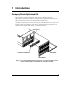
1 Introduction Compaq Rack-Optimized Kit The front bezel, control panel bezel, and LCD cover shipped with your HP NetServer LXr 8000 or 8500 were designed for an optimized look and fit in HP rack enclosures and were not designed for Compaq racks. Complete and mail the post card in the top tray of the HP NetServer to receive the kit that contains the nameplate, front bezel, control panel bezel, and LCD cover optimized for Compaq racks. Figure 1-1 shows these items.
Chapter 1 Introduction NOTE Until you receive the Compaq rack-optimized front bezel, control panel bezel, and LCD cover: • Leave the HP-optimized control panel bezel in place. • Do not close the front door (if any) of the Compaq rack because it would interfere with the HP-optimized control panel bezel. • Do not remove the HP-optimized front bezel.
Chapter 1 Introduction Table 1-1. Alternative Installation Operations Received Kit: Initial installation of HP NetServer with the Compaq rack-optimized kit Awaiting Kit: Initial installation of HP NetServer without Compaq rack-optimized kit, followed by later installation of kit 1. Remove bezel latch, control panel bezel, and LCD cover (Chapter 2). 1. Prepare Compaq rack (Chapter 3). 2. Install new LCD cover and new control panel bezel (Chapter 2). 2.
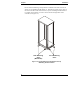
Chapter 1 Introduction Be sure that the stabilizing, anti-tip feature is installed on the rack enclosure in which you are installing the HP NetServer. This feature consists of two "feet" at the front of the base of the enclosure and, if you are installing this HP NetServer in a single rack enclosure, two "feet" each on the left and right sides of the enclosure (see Figure 1-2). Side Stabilizing "Feet" (Both Sides) Front Stabilizing "Feet" Figure 1-2.
Chapter 1 Introduction CAUTION If this HP NetServer is not installed according to these instructions, damage to the HP NetServer or accessories may result. Damage due to improper installation is not covered by the HP Warranty. Observe the precautions listed in this section to maintain the HP NetServer's reliability. When the HP NetServer LXr 8000 or 8500 is installed in a Compaq rack enclosure, certain requirements must be addressed to assure that the needs of the HP NetServer are met.
Chapter 1 Introduction Tools The following tools are required to install the HP NetServer in a Compaq rack: ® l T15 Torx driver l Small thin flat-bladed screwdriver l Pozidriv or Phillips screwdriver Needle-nose pliers may also be helpful. Terms Terms used in this document are defined in the table below. Table 1-2. Terms Term 8 Definition Cage nut Single nut designed to clip behind the rack column and accept a screw through the hole in the column.
2 Preparing the HP NetServer Overview of HP NetServer Preparation Follow the instructions in this chapter after you receive the Compaq rack-optimized kit. The existing LCD cover (metal housing around the LCD) on the front of the HP NetServer is too thick to accommodate the front bezel to be used in the Compaq rack. This chapter describes how to prepare the HP NetServer for the Compaq rack-optimized front bezel. The instructions in this chapter are summarized in the list below.
Chapter 2 Preparing the HP NetServer Disconnect the HP NetServer WARNING Before removing the covers, always disconnect the power cord and unplug telephone cables. Disconnect the power cord to avoid exposure to high energy levels that may cause burns when parts are short-circuited by metal objects, such as tools or jewelry. Disconnect telephone cables to avoid exposure to shock hazard from telephone ringing devices. Note that the power switch does not turn off the standby power.
Chapter 2 Preparing the HP NetServer Extend the HP NetServer If the HP NetServer is already installed in a Compaq rack (without a front bezel), do the following to extend the HP NetServer: 1. Remove the four screws that secure the HP NetServer to the rack columns, as shown in Figure 2-1. Figure 2-1.
Chapter 2 Preparing the HP NetServer 2. To extend the HP NetServer from the rack, pull on the handle indicated in Figure 2-2. Handle Figure 2-2. Pull the Handle to Extend the HP NetServer from the Rack CAUTION 12 When the HP NetServer is extended from the rack, do not lean on it or place extra weight on it.
Chapter 2 Preparing the HP NetServer Remove Bezel Latch If a bezel latch is mounted on the right side of the HP NetServer, remove it to avoid interference with the Compaq rack front bezel. To remove the bezel latch, remove the screw indicated in Figure 2-3. Figure 2-3.
Chapter 2 Preparing the HP NetServer Remove the Control Panel Bezel NOTE Do not remove the original HP rack-optimized control panel bezel until you have received the Compaq rack-optimized control panel bezel. Remove the existing control panel bezel, as shown in Figure 2-4. Push in on the snap latches on the left and right ends of the control panel bezel, and gently pull the control panel bezel away from the HP NetServer. Control Panel Bezel Snap Latch (2 Places) Figure 2-4.
Chapter 2 Preparing the HP NetServer Remove the Top Cover, Fan Cover, Fans, and Fan Cage Remove the entire top cover, fan cover, all fans, and the fan cage, as follows: 1. Remove the two screws at the front of the cover, then slide the cover back approximately one half-inch (1 cm), as shown in Figure 2-5. Screws Top Cover Figure 2-5. Removing the Entire Top Cover (HP NetServer LXr 8500 Shown) 2. Lift off the top cover, as shown in Figure 2-5. 3.
Chapter 2 Preparing the HP NetServer 4. Pull the fan cover forward, and then lift the front of it about 1 inch (3 cm). 5. Push the fan cover backwards, and lift it off. 6. Remove all six fans by pulling them straight up, as shown in Figure 2-7. CAUTION Remove all fans before you remove the fan cage. Otherwise, the fans will fall out, which may damage the fans and other equipment. Figure 2-7.
Chapter 2 Preparing the HP NetServer 7. Remove the three screws from the front of the fan cage, as shown in Figure 2-8. Figure 2-8. Removing the Fan Cage (HP NetServer LXr 8500 Shown) 8. Remove the two screws from the sides of the chassis, as shown in Figure 2-8. 9. Remove the fan cage by lifting it up and pulling its top slightly forward. CAUTION The light pipes on the underside of the fan cage are fragile. Be careful not to damage them.
Chapter 2 Preparing the HP NetServer Disconnect the LCD Cables A ribbon cable and a twisted-pair cable connect the LCD to the front panel board, as shown in Figure 2-9. (For clarity, the processor tray is not shown in the enlarged detail in the figure.) Front Panel Board Twisted-pair Cable Connector Ribbon Cable Connector Top Flap of Ribbon Cable Connector Processor Tray Figure 2-9.
Chapter 2 Preparing the HP NetServer Remove the Existing LCD Cover WARNING The LCD cover contains sheet metal with sharp edges. Handle it carefully to avoid injury. Do the following to disassemble the existing LCD cover: 1. Use a thin flat-blade screwdriver to bend the twelve spring fingers on the cover away from the LCD. The detail in Figure 2-10 shows six of the twelve spring fingers. Bend all twelve enough to reduce their spring tension. They do not have to actually stay bent back.
Chapter 2 Preparing the HP NetServer 3. Grasp the LCD assembly with both hands. Pull up firmly on the LCD assembly to lift it as high as possible. You may need to pull quite firmly and wiggle the LCD assembly to overcome the retaining spring shown in Figure 2-11. When the LCD assembly is lifted high enough, the upper two posts on the HP NetServer are in the wide part of the upper two slots on the LCD cover, and the lower posts are free.
Chapter 2 Preparing the HP NetServer Install the New LCD Cover WARNING The LCD cover contains sheet metal with sharp edges. Handle it carefully to avoid injury. Do the following to assemble the new LCD cover: 1. Orient the LCD board to the rear half of the new LCD cover, as shown in Figure 2-12. The spring finger on the side of the front half of the LCD cover must be in the lower half of the cover, as shown.
Chapter 2 Preparing the HP NetServer 2. Thread the LCD power cord and ribbon cable through the rectangular hole in the rear half of the new LCD cover, as shown in Figure 2-12. CAUTION Be careful not to pinch the LCD cables between the LCD board and the rear LCD cover. 3. Slide the LCD board into the rear half of the LCD cover, as shown in Figure 2-13. ◊ Place the LCD board under the two retainers. ◊ Place the LCD board in front of the three standoffs.
Chapter 2 Preparing the HP NetServer Post (4 Places) LCD Assembly Hole in Processor Tray for LCD Cables Figure 2-14. Attaching the LCD Assembly (HP NetServer LXr 8500 Shown) CAUTION When you attach the LCD assembly to the HP NetServer, be careful not to pinch the LCD cables between the LCD assembly and the front of the HP NetServer. 7. Position the slots on the rear half of the LCD cover over the posts on the processor tray.
Chapter 2 Preparing the HP NetServer Reconnect the LCD Cables CAUTION When connecting the LCD cables, push the connector straight into the socket. This protects the connector pins from being bent. Reconnect the LCD cables to the front panel board, as follows: 1. Push the ribbon cable connector onto the corresponding socket, as shown in Figure 2-15. Then push down gently on the top flap to secure the connector.
Chapter 2 Preparing the HP NetServer Reinstall the Fan Cage, Fans, Fan Cover, and Top Cover CAUTION The light pipes on the underside of the fan cage are fragile. Be careful not to damage them. To reinstall the fan cage, fans, fan cover, and top cover do the following: 1. Orient the fan cage as shown in Figure 2-16, being careful not to damage the light pipes on the underside of the cage. Figure 2-16. Reinstall the Fan Cage (HP NetServer LXr 8500 Shown) 2. Lower the fan cage into the chassis.
Chapter 2 Preparing the HP NetServer 3. Install all six fans. Orient them with their arrow labels pointing to the rear of the HP NetServer. The fans are keyed so that they must be oriented correctly before they can be inserted fully, with the top of the fan flush with the top of the fan cage. There is NO tactile or audible "click" when the fan is fully inserted. 4. Reinstall the fan cover, as shown in Figure 2-17. Align the tabs on its rear edge with the slots in the fan cage.
Chapter 2 Preparing the HP NetServer 5. Lower the top cover onto the top of the HP NetServer, about one half-inch (1 cm) to the rear of its normal position when closed. See Figure 2-18. Screws Top Cover Figure 2-18. Reinstalling the Top Cover (HP NetServer LXr 8500 Shown) 6. Push the top cover forward until the slots in its front edge line up with the screw holes on the chassis. 7. Reinsert the screws, as shown in Figure 2-18.
Chapter 2 Preparing the HP NetServer Attach the New Control Panel Bezel Attach the new control panel bezel, as shown in Figure 2-19. Push in the snap latches on the left and right ends of the control panel bezel, and gently push those latches into the two slots on the front of the HP NetServer indicated in the figure. Control Panel Bezel Snap Latch (2 Places) Figure 2-19.
3 Preparing the Rack Overview of Rack Preparation WARNING To prevent the rack from tipping over, be sure that the stabilizing, anti-tip feature is installed on this rack enclosure, as shown in Figure 1-2. Do the following to prepare the Compaq rack for the HP NetServer: l Determine where to install the NetServer in the rack. l Mark the installation holes. l Install the cage nuts. l Adjust the slides. l Mount the slides.
Chapter 3 Preparing the Rack To mark the slide mounting holes, refer to Figure 3-1 and do the following: 1. On the front columns, count up from the bottom of the installation location (which is the top of the unit below), marking the 4th and 6th holes. 2. On the rear columns, count up from the bottom of the installation location (which is the top of the unit below), marking the 4th and 6th holes.
Chapter 3 Preparing the Rack Install the Cage Nuts Once you have marked the twelve holes, install a supplied cage nut in each marked hole on all columns, as shown in Figure 3-2. Cage Nut Column Figure 3-2. Installing Cage Nuts Adjust the Slides Prepare both slides for mounting, as shown in Figure 3-3: Rear Flange Screws Front Flange Extendible Members Figure 3-3.
Chapter 3 Preparing the Rack 1. Loosen the two screws on the rear flange of the slide, but leave them in place. 2. Extend the rear flange by pushing it outward until the screws stop it. 3. Tighten the screws. NOTE The slides do not come apart; they are one piece. Mount the Slides 1. Orient each slide so that the front of the slide attaches to the front column and the rear attaches to the rear column. This ensures that, once installed, the slides will extend correctly toward the front of the rack.
4 Installing into the Rack Overview of Installation into Rack If the HP NetServer is not yet mounted in the Compaq rack, do the following to mount it: l Remove the power supply modules. l Mount the HP NetServer on the slides. l Reinstall the power supply modules. After the HP NetServer is mounted in the rack, do the following to install the Compaq rack-optimized front bezel: l Install the nameplate on the front bezel. l Install the front bezel.
Chapter 4 Installing into the Rack Before you lift the HP NetServer, remove the power supply modules from the rear of the HP NetServer to reduce the weight and improve stability, as shown in Figure 4-1. Figure 4-1. Removing Power Supply Modules (Shown for HP NetServer LXr 8500) WARNING Do not touch any metal object to the power supply connector contacts. High electrical charges may be stored in the module even after it has been removed. Fire or bodily injury may result if terminals are short-circuited.
Chapter 4 Installing into the Rack Mount the HP NetServer on the Slides 1. Verify that both slides are fully extended from the rack, as shown in Figure 4-2. Extended Slide Members Lifting Handles (2 more on other side) Figure 4-2. Lifting the Server Onto the Slide Members 2. Using at least two people, lift the HP NetServer by using the lifting handles on each side.
Chapter 4 Installing into the Rack Figure 4-3. Attaching the Slides to HP NetServer Chassis 3. Line up the mounting holes in the slide members with the holes in the HP NetServer chassis, insert the four screws on each side and tighten them, as shown in Figure 4-3. 4. Remove the two screws from each of the four lifting handles and remove the handles, as shown in Figure 4-4. Keep these handles and screws for later use, in case you need to remove the HP NetServer and ship it. Figure 4-4.
Chapter 4 Installing into the Rack 5. On both slide members, simultaneously depress the lockout releases shown in Figure 4-5. Then push the HP NetServer completely into the rack enclosure. Figure 4-5. Location of Lockout Releases 6. Install two screws through the two holes on either side of the HP NetServer front, as shown in Figure 4-6, and into the cage nuts in the columns (previously installed in Chapter 3). Figure 4-6.
Chapter 4 Installing into the Rack Reinstall Power Supply Modules Reinstall all power supply modules. To install a power supply module: 1. Pull down the handle on the new power supply module fully. 2. Insert the module in the power supply bay. 3. Slide the power supply module forward in the bay until it stops. 4. Lift the handle fully until it stops against the module. CAUTION When installing a power supply module, verify that the handle has latched the module fully into the power supply bay.
Chapter 4 Installing into the Rack Slots Holes for Studs Nameplate HP Logo Tabs Compaq Rack-Optimized Front Bezel Figure 4-7.
Chapter 4 Installing into the Rack Install the Compaq Rack Front Bezel Install the front bezel optimized for Compaq racks as follows: 1. Hold the bezel in front of the HP NetServer, as shown in Figure 4-8. Align the four studs on the back of the bezel with the four oval holes indicated in the figure. Figure 4-8. Installing the Front Bezel for Compaq Racks 2. Press the front bezel firmly into place.
A Warranty and Support Refer to the HP NetServer Warranty and Service/Support Booklet provided with your original HP NetServer system documentation for the warranty limitations, customer responsibilities, and other terms and conditions. CAUTION Improper installation of HP rack mount components into third party racks may result in unreliable operation or damage to the HP components. Repairs to HP components due to improper installation into third party racks are not covered under the HP warranty.
Appendix A Warranty and Support product by Customer from HP or Reseller. If HP or Reseller receives notice of such defects during the warranty period, HP or Reseller will either, at its option, repair or replace products that prove to be defective. Should HP or Reseller be unable to repair or replace the hardware accessory within a reasonable amount of time, Customer's alternate remedy shall be a refund of the purchase price upon return of the hardware accessory product.
Index A Accessories, 7 Adjusting rack slides, 31 American Power Conversion Corporation (APC), 7 Anti-tip feature, 6 B Bezel control panel, 14, 28 front, 9, 38, 40 Bezel latch, 13 C Cage nut, 8 Caution extended HP NetServer, 12 fan cage light pipes, 17, 18, 24, 25 fan removal, 16 improper installation, 7 LCD cables, 22, 23 LCD cover sharp metal, 19, 21 power supply module installation, 38 Compaq rack, 1, 5 door, 4, 7 installation holes, 29 installation requirements, 7 Compaq rack-optimized kit, 3 Connecting
Index LCD cover, 3, 9, 19, 20, 21, 22, 23 retainers, 22 slots, 20, 23 spring fingers, 19 standoffs, 22 Lifting handles, 36 Lifting HP NetServer, 35 Light pipes, fan cage, 17, 18, 24, 25 Lockout releases, 37 M Marking installation rack holes, 29 Mass storage devices, 7 Mounting HP NetServer on slides, 35 Mounting rack slides, 32 N Nameplate, 3, 38 Nameplate studs, 38 Nameplate tabs, 38 O Overview HP NetServer preparation, 9 installation into rack, 33 rack preparation, 29 P PDU (power distribution unit), 7 P