
HP Netserver LC II Installation Roadmap

1.Overview of HP NetServer LC II Features
2. Verify Contents
3. Obtain HP Navigator CD-ROM Release History
4. Connect Monitor, Keyboard, and Mouse
5. Prepare for Installation
6. Remove the Covers
7. Install Additional Memory
8. Install All Accessory Boards
9. Install Additional Mass Storage Devices
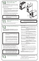
10. Replace All Covers and Connect All Cables
11. Verify Installed Accessories (Optional)
12. Configure the HP NetServer
13. Install in Rack (Optional)
Audience Assumptions
ESD Warning
This road map is intended for the person who installs, administers,
and troubleshoots LAN servers. Hewlett-Packard Company
assumes that you are qualified in the servicing of computer
equipment and trained in recognizing hazards in products with
hazardous energy levels.
This HP NetServer contains sensitive electronic devices that can be
damaged by electrostatic discharge (ESD). ESD hazards are a result
of installation or service personnel failing to ground themselves
properly. To be properly grounded, you must use a proper ESD wrist
strap and work surface grounded to the HP NetServer chassis.
LC II Installation Road Map
Table of Contents
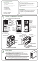
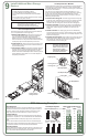
Overview of HP NetServer LC II Features
1
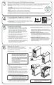
Serial B Port
Serial A Port
Parallel Port
Mouse Port
Keyboard Port
Monitor Port
Management Port for
management using
Integrated Remote Assistant
remote
console
Network
Connector
Power
Connector
Front View with
Mass Storage Shelves
Front View with
Hot Swap Subsystem
Rear View
Interior ViewFront Bezel and Covers Removed
Serial Number
Locked
Position
Unlocked
Position
Shelf 1 (Flexible Disk Drive)
Front Bezel Key Lock
Front Bezel
Power Switch and Power LED
Keyboard Lock Switch and Keyboard Lock LED
Shelf 2 (CD-ROM Drive)
Shelf 3 Shelf 3
Shelf 4
Hot Swap
Subsystem
Shelf 5
Shelf 6
Pedestal
Lock on
Locking Bar
System Board
CPU
CPU Extractor Handle
System Board
Terminator Board
CPU
SCSI Connector
Backplane Flexible Disk Drive (FDD) Connector
Disk Array Controller Board
(Optional, Slot 5)
Network Interface
Controller Board (Slot 6)
Retaining Latch
Voltage Regulator Module
Retaining Latch
Connector for External
Battery (Hidden)
Battery
Slot 1
System Switches
Backplane
Power Supply
Module
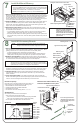
2
Verify Contents
1. Unpack and verify the contents of the shipping box against the Contents Checklist included
with your HP NetServer. If anything is missing or damaged, contact your reseller.
2. Mount the HP NetServer on the anti-tip pedestal unless you plan to install it in a rack
assembly. The instructions molded into the pedestal point toward the front of the pedestal, which holds
the front of the HP NetServer. Center the HP NetServer on the centerline of the pedestal with the front
of the HP NetServer extending 2 inches (5 cm) beyond the front of the pedestal. Then push the HP
NetServer in toward the rear of the pedestal until it locks into place.
Pedestal
NOTE If you plan to install the HP NetServer in a rack assembly, wait to do that in Section 13:
"Install in Rack (Optional)" after all options are installed. Refer now to the
to determine whether to configure the HP NetServer before or
after you install it in the rack assembly. Also refer to the rack installation kit instructions.
HP NetServer
Rack Installation Road Map