
HP Netserver LC II Installation Roadmap

7
DIMM Installation Rules
!
!
!
Use only HP DIMMs listed on the Technical Reference Label located inside
the HP NetServer top cover, in Information Assistant, or on Order Assistant.
DIMMs can be 32 MB, 64 MB, or 128 MB in any combination.
DIMMs can be installed in any order in any of the four DIMM sockets.
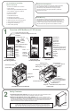
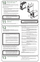
1. Remove the system board:
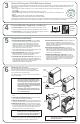
2. Install the DIMMs:
3. Reinsert the system board:
If you have not yet removed the top cover, remove it as
described in Section 6: "Remove the Covers." Lift the the retaining latches to start raising the
system board. Grasp the metal bracket at the top of the system board, lift the system board
out of the HP NetServer, and place it component-side up on the static-dissipating work
surface (antistatic mat). Lay the system board flat, with the metal crosspiece on the top rear
corner of the system board extending OFF the work surface, as shown at right.
On a DIMM socket, spread the two retaining clips outward. Align the
notches on the DIMM with the keys on the socket. Hold the DIMM at 90 degrees to the
system board, and insert the DIMM fully into the socket until the retaining clips close. If the
clips do not close, the the DIMM is not inserted correctly.
Insert the plastic rails on the back side of the system
board into the metal guides on the side of the chassis, and push the system board down into
the HP NetServer as far as follows:
If you will install an accessory board in slot 5 or 6, leave the system board in its raised
position, extending about 5 inches (about 12 cm) above the top of the chassis.
Otherwise, hold the handles of the retaining latches vertical, and push the system board
down to seat it firmly in its slot. Then, lower the retaining latches simultaneously to secure
the board.
!
!
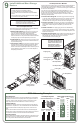
Install All Accessory Boards
Install Additional Memory
8
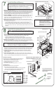
Available Slots:
Six accessory board slots exist on the backplane:
Slots 2 through 6 accept 32-bit PCI boards:
Slot 6 has a network interface controller board (NIC) preinstalled.
Slot 5 may have optional disk array controller board (DAC).
Slot 1 accepts a 16-bit ISA board or a 32-bit PCI board.
!
!
Backplane:
1. Remove covers and raise system board:
2.Read the documentation
If you have not yet removed the top
cover and side cover, remove them as described in Section 6: "Remove the Covers." Before
installing a board in slot 5 or 6, raise the system board if it is not already raised:
included with each accessory board. Follow any special
instructions and installation recommendations. Some boards have preferred slot locations. If
not, consider the boot order when selecting the slot to use in the backplane.
!
!
Lift the the retaining latches to start raising the system board.W
Grasp the metal bracket at the top of the system board, and lift the system board to its
raised position, extending about 5 inches (about 12 cm) above the top of the chassis.
3. Remove the slot cover
4. Install the boards:
5. Lower the system board:
for each slot to be used, and store it for future use. If you are
installing any full-length PCI boards, also remove the board retainer, shown below. Push on
the button on the board retainer to release it, and then lift it up and out of the board guide.
Insert each board in the desired slot, and fasten the board's
mounting screw. Connect any required cables to the boards. If you removed the board
retainer, reinstall it.
If you raised the system board, lower it by holding the
handles of the retaining latches vertical and pushing the system board down to seat it firmly
in its slot. Lower the retaining latches simultaneously to secure the board.
NOTE For a list of boards HP has tested, see Help topic "Tested Parts
List" on the HP Navigator CD-ROM. The Readme file on the HP
Navigator CD-ROM contains the latest configuration information.
NOTE If you install an ISA non-Plug-and-Play board, you MUST reserve system
resources (some or all of: memory addresses, I/O addresses, IRQs, and DMA
channels) for it. Write down that information now for reference when you reserve
system resources in Section 12: "Configure the HP NetServer."
An accessory board can be
identified by the offset of the
bracket and the shape of the
edge connector:
Boot device priority:
Boot order for PCI controllers is determined by slot location. The
system searches for a bootable device in the following order:
1. IDE CD-ROM drive with a bootable CD-ROM
2. Flexible disk drive with a bootable flexible disk
3. Embedded SCSI controller
4. PCI boards in slots in the following order: 6, 5, 4, 3, 2, 1
PCI 6 - 32-bit
System
Board
Slot
PCI 5 - 32-bit
PCI 4 - 32-bit
PCI 3 - 32-bit
PCI 2 - 32-bit
PCI 1 / ISA -
16-bit ISA or
32-bit PCI
SCSI ConnectorIDE ConnectorFDD Connector
Typical Accessory Board
Typical
Slot Cover
Backplane
Mounting Screw
Retaining Latch
Retaining Latch
DIMM
Slots
Board Guide and Board Retainer are
behind the HP NetServer front panel:
System Board in
Raised Position
CAUTION Only install DIMMs on a system board
lying flat on a static-dissipating work
surface. The metal crosspiece
indicated by the arrow in the figure
above must be OFF the work surface.
Otherwise, flexing can damage the
system board.
DIMM Slot 0
Clips
DIMM Slot 1
DIMM Slot 2
DIMM Slot 3
DIMM
Notches
System Board
Crosspiece must be OFF work surface.
Static-dissipating Work Surface
Metal Bracket
Board Guide
Backplane
Board
Retainer
Top View of Board Retainer
Push Button to Release
Rear Side of
Front Panel
PCI Board-
left-side offset
ISA Board-
right-side
offset