
HP Netserver LC II Installation Roadmap
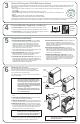

SCSI Addresses
Jumper Settings
SCSI Termination
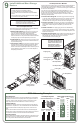
Each SCSI device must have a unique SCSI address (ID). This address
dictates the SCSI device's boot priority and is set by jumpers located on
the device, usually on the underside. Switches on the back of the hot
swap subsystem set its SCSI addresses, as shown at near right.
The table to the far right shows typical jumper settings for wide (68-pin)
SCSI devices. Jumpers A0, A1, A2, and A3 determine the SCSI address.
Set the SCSI termination enable jumper (TE) to OFF, as shown in the
table.
Refer to the SCSI device documentation for the recommended jumper
settings. Refer to the Technical Reference Label inside the top cover and
to Information Assistant for the recommended SCSI addresses.
The HP NetServer SCSI cable is terminated, either by a terminator on the
cable itself, or by the hot swap subsystem.
Verify that no added SCSI devices are terminated.
Verify that jumper TE is set to
OFF.
9
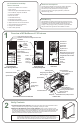
Install Additional Mass Storage
Devices
NOTE For certain mass storage configurations you may
need additional cables or adapters. See Order
Assistant and Information Assistant for
configuration information and part numbers.
8
9
10
11
12
13
14
15
TE
A0
A1
A2
A3
SCSI
Address
Jumpers
0
1
2
3
4
5
6
7
TE
A0
A1
A2
A3
reserved
SCSI
Address
Default SCSI Addresses 1, 0, 3:
Alternate SCSI Addresses:
1, 2, 3 9, 10, 11 9, 8, 11
Jumpers
Hot Swap Subsystem Wide (68-Pin) SCSI Devices
Non-Hot Swap SCSI Drives
1. Set the SCSI address:
2. Install the drive:
3. Connect the cables:
HP SCSI tape drives and hard disk drives for the HP NetServer
LC II come preinstalled in mass storage trays.
Set the jumpers on the drive to
an unused SCSI address. Refer to the drive's installation
guide, the Technical Reference Label inside the HP
NetServer top cover, and the SCSI Addressing Examples
below for instructions. Verify that the drive's SCSI termination
enable jumper (TE in the example below) is set to OFF.
Remove the cover from an empty mass
storage shelf, and store it for future use. Install the drive in its
tray in the shelf opening.
Connect SCSI and power cables to
the drive. Refer to the Technical Reference label for cabling
examples. For narrow (50-pin) SCSI tape drives, use the
wide-to-narrow SCSI cable adapter with the white body on the
the HP NetServer's SCSI cable. Do not use that adapter for
wide (68-pin) SCSI drives.
Preinstalled Devices
!
!
!
!
A flexible disk drive is preinstalled in Shelf 1.
An IDE CD-ROM drive is preinstalled in Shelf 2.
Some models have a SCSI hard disk drive preinstalled in
Shelf 3.
Some models have a hot swap subsystem that can support
up to three hot swap drive modules.
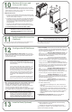
SCSI Addressing Examples
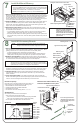
Hot Swap Disk Drive Modules
To remove the locking bar:
To remove a module:
To install a module:
To replace the locking bar:
Hot swap disk drive modules can only be installed in hot swap subsystems.
The three trays in the optional HP NetServer LC II hot swap subsystem
have SCSI addresses pre-set to 1, 0, and 3 from left to right, as viewed from
the front of the HP NetServer.
If you have a non-hot swap SCSI device with SCSI address 0, 1, or 3,
change it or the SCSI addresses on the hot swap subsystem so that they
do not conflict. To change the hot swap SCSI addresses, move the
switches on the rear of the hot swap subsystem, as shown in the SCSI
Addressing Examples below.
Insert the key (provided in the key bag
on the rear of the HP NetServer) into the lock on the locking bar (shown
below). Press in on the lock, and then unlock it by turning the key
clockwise. Slide the locking bar to the left, and then lift it straight up.
If a shipping plug (shown in the detail below)
secures the locking lever, remove it. Depress the locking tab atop the
locking lever, lift the locking lever completely up, and remove the
module.
If a shipping plug (shown in the detail below)
secures the locking lever, remove it. Lift the locking lever up completely,
insert the module into the hot swap tray in the hot swap subsystem, and
depress the locking lever.
Align the tabs on the locking bar (shown
below) with the slots in the trim bezel. Insert the locking bar, and then
slide it to the right. Insert the key into the lock, and turn it
counterclockwise to lock the locking bar.
CAUTION Depress the locking lever
carefully to avoid breaking it.
If it is difficult to depress, the
module is in too far or is not
seated properly. Lift the
locking lever completely up,
and reinsert the module.
Shipping Plug
Locking Lever
Locking Tab
Hot Swap Module
Hot Swap Subsystem
Locking Bar
Hot Swap Module
Covers of mass
storage shelves
Trim BezelSlots
Lock