HP NetServer LPr Installation Guide HP Part Number D6129-90000 Printed October 1998
Notice The information contained in this document is subject to change without notice. Hewlett-Packard makes no warranty of any kind with regard to this material, including, but not limited to, the implied warranties of merchantability and fitness for a particular purpose. Hewlett-Packard shall not be liable for errors contained herein or for incidental or consequential damages in connection with the furnishing, performance, or use of this material.
Contents Chapter 1 Setting Up the HP NetServer LPr.................................................. 1 Before You Begin .......................................................................................... 1 Setup Steps................................................................................................... 1 Preparations.............................................................................................. 1 Install Options .............................................................
Contents Removing Hot-Swap Drives......................................................................... 30 Chapter 5 Installing Additional Memory...................................................... 31 Introduction ................................................................................................. 31 Tools Required ............................................................................................ 31 Installing Additional DIMMs ....................................................
Contents Prevent Rack Tip-Over, Equipment Damage, and Injury ............................. 62 Tools Required ............................................................................................ 62 Installation Basics........................................................................................ 62 HP NetServer LPr Rack Mount Parts List ................................................ 63 Installing the HP NetServer LPr in the Rack ................................................
Contents Chapter 12 Information Assistant................................................................ 91 Overview ..................................................................................................... 91 Using Information Assistant ......................................................................... 91 Getting Help ............................................................................................ 91 Finding Information ......................................................
Contents Power Line Harmonics............................................................................116 Notice for Korea .....................................................................................116 Notice for Taiwan: Class A Warning Statement ......................................117 Notice for European Union .....................................................................117 Notice for the United Kingdom: General Approval .................................
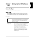
Chapter 1 Setting Up the HP NetServer LPr Before You Begin Read this chapter. Follow the steps described here. Setup Steps It is important that you follow the setup steps in the exact order shown below. Skip any steps that do not apply to you. To provide further details, these steps include references to other sections of this manual and to other documents. Preparations CAUTION Prepare Site The HP NetServer LPr weighs approximately 38 pounds. Use appropriate lifting precautions when you move it.
Chapter 1 Verify Contents Setting Up the HP NetServer LPr Unpack the contents of the shipping box. Verify the contents of the shipping box against the Contents Checklist included with your HP NetServer LPr. If anything is missing or damaged, call your reseller. Save Packaging Support Information 2 Store the empty boxes and packing material in a safe place. This is especially important if you plan to ship the HP NetServer LPr elsewhere for final installation.
Chapter 1 Setting Up the HP NetServer LPr Support Information (continued) ◊ HP NetServer LPr Installation Guide This document supports installation, hardware upgrades, configuration, and troubleshooting of systems based on the HP NetServer LPr. ◊ Information Assistant A hypertext system that contains the entire set of documentation for the LPr. It is on the HP NetServer Online Documentation CD-ROM. See Chapter 12 for details on using this.
Chapter 1 Setting Up the HP NetServer LPr Remove Top Cover See Chapter 3, "Opening and Closing the HP NetServer LPr." Add Memory Use HP DIMMs only. DIMMs may be installed in any combination, in any sockets. For details see Chapter 5, "Installing Additional Memory." Add Video Memory Video memory upgrade expands the frame buffer from 1 to 2 MB and supports 1280 x 1024 displays. For details, see Chapter 6, "Installing Additional Video Memory.
Chapter 1 Add Boards Setting Up the HP NetServer LPr BE SURE to remove handles from PCI cards. Note that there are specific subsections in Chapter 7 dealing with installation of the HP NetRAID and Remote Control cards on the PCI bus. See the readme file on HP NetServer Navigator CD-ROM for recommended slots. Note that slot assignments of disk drive controller cards affects boot order. For details see Chapter 7, "Installing Additional Boards.
Chapter 1 Setting Up the HP NetServer LPr Mounting the LPr in a Rack NOTE You may want to configure and test the NetServer LPr before mounting it in the rack, or you may first mount it in the rack. Mount the Server in the Rack Refer to the Installation Roadmap that comes with the rack. Use the template that comes with the mounting hardware to determine rack nut and screw location and order of attachment.
Chapter 1 Setting Up the HP NetServer LPr Configuring the System 1) Connect Peripherals For detail on rear panel interface connectors, see Chapter 2. For details on connecting the keyboard, mouse, monitor, and UPS, see Chapter 10. 2) Boot the HP Navigator CD-ROM Turn on the monitor. Press the power-on button on the HP NetServer, and press the eject button on the CD-ROM drive. NOTE: Using the low profile CD-ROM drive is slightly different than full-height units.
Chapter 1 4) Setting Up the HP NetServer LPr Run Configuration Assistant (continued) After you select Configuration and Installation Assistant, you will have the option of using the Hardware Verification and Labeling utility. This utility allows you to check the connection of the LPr to peripheral subsystems such as rack storage units. Custom configuration mode and Replication configuration mode are also available. Refer to Chapter 11 for details.
Chapter 1 Setting Up the HP NetServer LPr 7) Read Configuration Advisor Configuration Advisor will appear. It provides information on optimizing hardware configuration and resource settings. It includes notes on specific operating systems. 8) Configure Integrated Remote Assistant If you plan to manage the HP NetServer LPr remotely, refer to the HP NetServer Server Management Reference Guide.
Chapter 1 13) Install Information Assistant (Optional) 14) View Order Assistant (Optional) Setting Up the HP NetServer LPr Information Assistant will help you support your HP NetServer. It is easier to use from a standalone system, rather than from the HP NetServer you are installing. Install Information Assistant from the HP NetServer Online Documentation CD-ROM onto the client system you will be using to manage your new NetServer. This is on the World Wide Web at: http://www.hp.
Chapter 2 Controls, Indicators, and Ports Front Panel Before installation, familiarize yourself with the HP NetServer LPr’s switches and LED (Light Emitting Diode) indicators. Figure 2-1.
Chapter 2 Controls, Indicators, and Ports Figure 2-2. Control Panel Table 2-1. Control Panel Switch and Indicator Definitions Control / Indicator 12 Description / Definition Power On/Off Switch Momentary switch. When pressed, moves power status back and forth between System Power and Standby Power. System Power allows full system operation; Standby Power enables remote system monitoring only. Power On/Off LED Green when System Power on.
Chapter 2 Drive Error LED Controls, Indicators, and Ports LED flashes red to indicate that one of the two drives in the hot-swap bays has failed and must be replaced. LED flashes yellow to indicate that one of the two drives is predicted to fail and should be replaced. You may have time to back up the drive before replacing it. NOTE: You may have to remove the front bezel to see the specific drive LEDs and determine which device is in trouble.
Chapter 2 Controls, Indicators, and Ports Rear View Refer to Figure 2-3 on the next page. 14 • The Management Port connector supports Integrated Remote Assistant and links the NetServer to a console for real time monitoring and diagnosis of system operation. • The Network Port consists of an RJ-45 connector supporting 10/100 BaseT Ethernet. It is the rear panel of a Network Interface Card in slot # 4 of the PCI expansion bus. • The Serial B Port is a standard serial port.
Chapter 2 Controls, Indicators, and Ports Figure 2-3. Rear Panel and Ports Table 2-2. Rear Panel Indicator Definitions Indicator Definition Link LED This LED goes on to indicate that both the network adapter in the LPr and the network switch are receiving power and that they are properly connected. Activity LED This LED flashes to indicate data transfers to/from the LPr network adapter. The rate of flashes varies directly with network traffic.
Chapter 2 Controls, Indicators, and Ports Power-Up and Power-Down Procedures Power-Up Procedure NOTE Turn on power to the monitor connected to the LPr before you power-on the LPr. This allows proper auto-configuration of video output of the LPr as it boots up. When you press the power button on the control panel, the LPr powers up and loads the operating system. The system runs a set of diagnostic tests (POST) during this process. For details refer to Chapter 13, "Troubleshooting.
Chapter 3 Opening and Closing the HP NetServer LPr Removing and Replacing the Front Bezel Remove or replace the NetServer LPr front bezel by snapping it on or off at the points indicated in Figures 3-1 and 3-2. Use the slots on the side of the bezel to grasp it. For details on removing the sever chassis from the rack, see the end of Chapter 9. Figure 3-1.
Chapter 3 Opening and Closing the HP NetServer LPr Figure 3-2. Replacing the Front Bezel NOTE 18 Install the front bezel on the LPr chassis after the chassis is mounted in the rack.
Chapter 3 Opening and Closing the HP NetServer LPr Removing and Replacing the Top Cover WARNING Be sure to disconnect the power cable from the rear panel before removing the top cover. Remove To remove, follow these steps: 1. Turn the thumbscrews at the rear of the enclosure counter-clockwise until they turn freely. Pull the top cover towards the rear. Figure 3-3.
Chapter 3 Opening and Closing the HP NetServer LPr 2. Lift the top cover away from the rest of the chassis to remove. Figure 3-4.
Chapter 3 Opening and Closing the HP NetServer LPr Replace 1. When replacing the top cover, make sure that all cables and the system board ejector levers are out of the way. 2. Align the front lip of the top cover so it will slide under the front panel edge. 3. Push the top cover forward and down until all edges are evenly aligned on the enclosure. 4. Turn the thumbscrews at the rear of the enclosure clockwise to tighten. Figure 3-5.
Chapter 4 Installing Mass Storage Devices Introduction The HP NetServer LPr comes with built-in CD-ROM and floppy diskette drives along with two hot-swap SCSI drive bays for LVDS (low voltage differential) low profile Ultra-2 SCSI devices. The same SCSI channel supporting the hot-swap cages may be extended to external devices via a standard 68-pin wide SCSI connector on the rear panel. See Figure 2-3 for SCSI connector location or the rear panel.
Chapter 4 Installing Mass Storage Devices Tools Required No tools are required to remove and replace hard drives from the hot swap bays. Installation Basics Drive Mirroring You may choose to use hardware to mirror your boot disk in the two hot swap bays (RAID level 1). To do this you must install an HP NetRAID card on your PCI bus and configure the system appropriately. See Chapter 7, "Installing Additional Boards.
Chapter 4 Installing Mass Storage Devices Hot-Swap Drive Bay Addresses The hot-swap bays are addressed from left to right as 0 and 1. The system will default to booting from the drive with SCSI ID 0 on the left bay. SCSI ID 1 SCSI ID 0 Figure 4-1. Hot-Swap Bays Other SCSI Device Addresses Other SCSI devices connected to LPr’s embedded SCSI channel can never use device ID 7 (the embedded SCSI controller). Other SCSI devices can use device IDs 0 and 1 if those hot-swap bays are not in use.
Chapter 4 Installing Mass Storage Devices Configuring the SCSI Host Adapter In order to verify or modify SCSI host adapter settings, or to low-level format SCSI disks or verify SCSI media, run the Symbios Configuration Utility. See Chapter 11, "Configuring the NetServer LPr," for further information. Installing Hot-Swap Drives CAUTION Protect the drive from static electricity by leaving it in its anti-static bag until you are ready to install it.
Chapter 4 Installing Mass Storage Devices Removing a Filler Panel 1. Remove filer panels: • Press the locking latch and insert your fingers. Using your fingers, pull the filler panel straight out. NOTE Leave the filler panels in place unless you are installing a SCSI device. They are required for proper ventilation. Figure 4-2.
Chapter 4 Installing Mass Storage Devices Readying the Drive for Installation 2. On the drive, press the locking latch in and pull the ejector handle out as far as it can go, as shown in Figure 4 -3. CAUTION Be careful when you open the ejector handle. Extreme force can snap off the handle. Locking tab retracts when the ejector handle is open Light Pipes (fragile) Ejector Handle Locking Latch Figure 4-3.
Chapter 4 Installing Mass Storage Devices Installing Hot-Swap Drives 3. Slide the drive slowly into the hot swap bay until it stops. See Figure 4-4. CAUTION Be careful not to damage the light pipes as you insert the drive. They are very fragile. You must insert the drive slowly and gently . If the drive is inserted too quickly when the system is on, in-rush current can cause the power supply to shut down. 4. Press the ejector handle in until you feel the latch click into place.
Chapter 4 Installing Mass Storage Devices Removing Hot-Swap Drives CAUTION You must remove the drive slowly to ensure that the drive heads are parked prior to removal. Be sure to follow these instructions carefully to prevent handling damage such as head slaps or head actuator unlocking. 1. To unlock the drive, push the locking latch in and then pull the ejector handle toward you. 2. Gently pull the drive out about an inch to disengage the power connection. 3.
Chapter 5 Installing Additional Memory Introduction The NetServer LPr’s main memory is implemented with 5V SDRAM DIMMs (Dual In-Line Memory Modules). The NetServer LPr ships with at least 64 MB of main memory and supports up to 1 GB. Memory is available in the following DIMM capacities: 64, 128, and 256 MB. There are four DIMM sockets on the system board. See Figure 5-1 for socket location. DIMMs may be installed in any combination in any socket.
Chapter 5 Installing Additional Memory WARNING The power supply will continue to provide standby current to the NetServer LPr until the power cable is disconnected. 4. Remove the NetServer from the rack. See the last section in Chapter 9, "Removing the NetServer from the Rack." 5. Remove the top cover from the NetServer (see Chapter 3, "Opening and Closing the HP NetServer LPr"). CAUTION Wear a wrist strap and use a static-dissipating work surface connected to the chassis when handling components.
Chapter 5 Installing Additional Memory c. Spread the two retaining clips on the socket outward. d. Align the notches on the DIMM with the keys on the socket. e. Holding the DIMM at 90 degrees to the system board, press the DIMM fully into the socket until the retaining clips close. If the clips do not close, the DIMM is not inserted correctly. Figure 5-2.
Chapter 5 Installing Additional Memory DIMM Notches Keys Retaining Clips Figure 5-3. Inserting a DIMM into a Connector 8. Repeat step 2 to install all of the DIMMs for your memory configuration. 9. If you are not installing any other options, replace the top cover. See Chapter 3, "Opening and Closing the HP NetServer LPr.
Chapter 5 WARNING Installing Additional Memory The power supply will continue to provide standby current to the NetServer until the power cable is disconnected. 4. Remove the NetServer from the rack. See the last section in Chapter 9. 5. Remove the top cover from the NetServer. See Chapter 3 for details. 6. Open the retaining clip s just enough so that you can lift the top edge of the DIMM away from the clips. 7. Lift the DIMM completely away from the socket. 8.
Chapter 6 Installing Additional Video Memory Introduction The HP NetServer LPr comes standard with a 1 MB frame buffer to support video displays of 1024 (horizontal pixels) x768 (vertical lines) x 256 (colors per pixel) at refresh rates up to 72 Hz. You can upgrade the frame buffer to 2 MB to support 1280 x 1024 by adding two memory chips. Tools Required • If removing the NetServer from the rack is necessary, use a T25 Torx driver.
Chapter 6 Installing Additional Video Memory 5. Remove the top cover from the NetServer. See Chapter 3 for details. CAUTION Wear a wrist strap and use a static-dissipating work surface connected to the chassis when handling components. Ensure that the metal of the wrist strap contacts your skin. 6. Locate the video memory chip sockets (see Figure 6-1). 7. Carefully remove the video memory chips from their packaging.
Chapter 7 Installing Additional Boards Introduction The HP NetServer LPr includes four PCI slots; one (over the system board) is taken by the Network Interface Controller (NIC) but can be used by other small PCI boards. This chapter tells how to use the three available expansion slots.
Chapter 7 Installing Additional Boards Installing PCI Cards Be sure to remove handles from PCI cards. Remove Card Handle Figure 7-1.
Chapter 7 Installing Additional Boards To install a PCI card: 1. Log off all users. Back up files. Follow instructions in your network operating system (NOS) documentation to gracefully shut down all networking software and applications. 2. Press the power switch on the HP NetServer’s control panel when prompted by the operating system. 3. Disconnect the power cables and signal cables and, if necessary, label them to support reassembly.
Chapter 7 Installing Additional Boards Figure 7-2. Remove PCI Card Access Panel 6. Apply pressure at the top of the PCI access cover to pop it out. 7. Read the documentation that is included with the PCI card. Note any special instructions. NOTE Adding a PCI-to-PCI bridge card to the HP NetServer may alter the server’s boot order. This boot order can be changed using the SETUP utility (press [F2] during the boot process).
Chapter 7 Installing Additional Boards Slot 3 Slot 2 Slot 1 Figure 7-3. PCI Slots NOTE For slot recommendations for specific PCI cards, see the Readme file or Configuration Advisor on your HP NetServer Navigator CD-ROM (for instructions see the "Configuring the System" subsection in Chapter 1). 9. Use the T15 driver to remove the PCI slot cover for each slot to be used, and store it for future use. 10. Use the T15 driver to remove the PCI retaining bracket and the screw holding it.
Chapter 7 Installing Additional Boards Figure 7-4.
Chapter 7 Installing Additional Boards 11. Position the PCI card, component side up, and slide it into the slo t. CAUTION Do not bend the PCI card to fit it into the slot. Check to make sure you removed any handles or board extenders as shown in Figure 7-1. Figure 7-5. Inserting a PCI Card 12. Use the T15 driver to screw the PCI card rear panel to the I/O panel at the rear of the LPr chassis. Refer to Figure 7-5. 13. Position the PCI retaining bracket and screw it down with the T15 driver. 14.
Chapter 7 Installing Additional Boards Removing PCI Cards Apply the same steps as in the installing procedure and simply remove the PCI card and the PCI retaining bracket. Replace the slot cover. See the preceding section for details. Installing a Remote Control Card Refer to the Top Tools Administration Guide for Remote Control along with the upgrade kit documentation for information on the remote control card. 1.
Chapter 7 Installing Additional Boards Installing an HP NetRAID Card To install a PCI Drive Access Controller (DAC) that will connect only with external devices, follow the instructions given in the previous pages for any PCI card. To install an HP NetRAID card that will mirror to the drives in the LPr’s two hot-swap bays, follow these steps: NOTE If there are other SCSI controllers on the PCI bus, the slot will affect boot order.
Chapter 7 Installing Additional Boards 2. Connect the SCSI cable to a SCSI channel connector on the NetRAID card. To choose a channel refer to HP NetRAID Series Installation and Configuration Guide (January 1998). CAUTION Do not bend the PCI card to fit it into the slot. Check to make sure you removed any handles or board extenders as shown in Figure 7-1. Figure 7-8.
Chapter 7 Installing Additional Boards 3. Disconnect the SCSI cable from the embedded SCSI controller on the I/O or "Riser" card. Figure 7-9. Disconnecting the SCSI Cable from the Embedded SCSI Controller 4. Follow instructions in the HP NetRAID documentation to set up the selected SCSI channel for mirroring .
Chapter 7 Installing Additional Boards 5. If you wish to continue to use the embedded SCSI controller to connect to external SCSI devices (a tape drive for example), you will have to order an accessory kit with a special SCSI cable that provides termination at the end opposite the SCSI terminator card. Figure 7-10 shows this cable after installation. Remove the adhesive strip from the terminator block and stick it on the floor of the LPr chassis in the area outlined by scribe lines.
Chapter 8 Installing Additional Processors Introduction The NetServer LPr supports up to two processor modules. Processor modules are available at different clock speeds. Both processor modules must operate at the same clock frequency. The processor upgrade kit includes the HP NetServer Navigator CD-ROM. Boot with this CD-ROM after installing the additional processor to update the BIOS.
Chapter 8 Installing Additional Processors The upgrade kit should include : • Processor Module • Voltage Regulator Module (VRM) • HP NetServer Navigator CD-ROM • HP NetServer LPr Processor Upgrade Guide NOTE Be sure to keep the bag around the processor sealed until you are ready to install the module. Open the NetServer LPr 1. Log off all users. Back up files.
Chapter 8 Installing Additional Processors Determine Where to Place the Processor Module 1. Locate the system board components that support the processor module upgrade. NOTE Be sure that the VRM and the processor module associated with it are both in primary or secondary slots. Figure 8-1.
Chapter 8 Installing Additional Processors 2. Check the processor clock switch settings and determine the clock speed of the primary processor module now on the system board. Figure 8-2. Processor Module Switch Settings 3. Check your upgrade kit to ensure that the additional processor module supports the same or higher clock rate. NOTE If you have two modules in your system with different clock rates, the switch setting must be for the lower of the two. 4.
Chapter 8 Installing Additional Processors 1. Remove the terminating resistor module from the secondary processor slot as shown in the following illustration. Hold the resistor module by its edges and gently pull directly upwards. Figure 8-3.
Chapter 8 Installing Additional Processors 2. Align the VRM card on the secondary VRM slot. Note that the component side should face towards the center of the enclosure like the VRM already installed. CAUTION Do not touch the components as you push the VRM card down into the socket. 3. Gently push the VRM down into the socket until it is seated completely. Make sure the VRM connector latch (see Figure 8-5) is raised to lock position. 4.
Chapter 8 Installing Additional Processors 6. Move the light blue plastic levers as shown to fully seat the processor module. VRM Connector Latch Move levers to upright position to seat processor module. Figure 8-5. Levers for Seating the Processor Module NOTE Be sure that the VRM and the processor module associated with it are both in primary or secondary slots. Upgrading the Firmware Load the HP NetServer Navigator CD-ROM and then power on the LPr.
Chapter 8 Installing Additional Processors Re-installing the NOS You may have to re-install your Network Operating System in order to use the additional processor. If you have gone from a uni-processor to multi-processor configuration, check your NOS documentation or the Readme First file and Configuration Advisor utilities on the HP NetServer Navigator CD-ROM. Removing a Processor Module Use the same procedure as above, and simply remove rather than add.
Chapter 9 Mounting the HP NetServer LPr in the Rack Overview Figures 9-1 and 9-2 (following page) present a visual summary of LPr rack mounting hardware. Figure 9-1.
Chapter 9 Mounting the Server in the Rack Rear Column Rail Bracket Rack Nut Foot LPr Rear Panel Note that brackets are installed to dampen vibration Figure 9-2.
Chapter 9 Mounting the Server in the Rack Rack Types HP Rack Systems This chapter shows mounting of the HP NetServer LPr into HP Rack System/E and Rack System/U. The same instructions and hardware will work with an earlier HP rack type, designated HP Rack System. Figure 9-3 shows the visible difference in these types. HP Rack System HP Rack System/E HP Rack System/U Figure 9-3. Distinguishing HP Rack Systems Alternate Racks The HP NetServer LPr may be installed in other racks.
Chapter 9 Mounting the Server in the Rack Prevent Rack Tip-Over, Equipment Damage, and Injury WARNING To prevent the rack from tipping over, extend the anti-tip foot from under the front and/or rear of the enclosure prior to mounting any components. Also lower the leveler feet at the four corners of the rack to improve stability and prevent the rack from rolling away as devices are inserted into their rack mounts. Failure to use the anti-tip foot and leveler feet could result in serious injury.
Chapter 9 Mounting the Server in the Rack • Air Flow. As you mount equipment in the rack, make sure that you allow enough air flow for safe operation of the equipment. • Mechanical Loading. Uneven mechanical loading within the rack can cause hazardous conditions. Plan the placement of equipment in the rack to make sure that this problem does not occur. Mount the heaviest components in the bottom of the rack. • Circuit Overloading.
Chapter 9 Mounting the Server in the Rack Installing the HP NetServer LPr in the Rack Step 1: Determine the rack configuration. Use the HP Rack Assistant software to determine where in the rack to mount the HP NetServer LPr. You may use tape or a marker pen to mark the bottom of the two EIA units required by the LPr. NOTE The HP NetServer LPr is two EIA units high. On the outside face of the rack, the EIA spaces are labeled from bottom to top in ascending order.
Chapter 9 Mounting the Server in the Rack Step 2: Use the template to identify the two EIA spaces. Note that the EIA space boundaries are marked on the rack. On HP Rack System/E, you will find the EIA spaces labeled from bottom to top in ascending order. Figure 9-4. EIA Space Markings The template is two EIA units high. Use it to determine which screw holes to install rack nuts on.
Chapter 9 Mounting the Server in the Rack Step 3: Place rack nuts on front and rear columns. Place the rack nuts on the front columns : • NOTE Use the template or locate the bottom of the EIA spaces to be occupied by the LPr and count up to holes 2, 3, and 5. Place rack nuts on these holes. The threaded nut part of the rack nut must be behind the outside face of the columns. Figure 9-6.
Chapter 9 Mounting the Server in the Rack Place rack nuts on the rear columns: • Use the template or locate the bottom of the EIA spaces to be occupied by the LPr and count up to holes 2, 3 and 4. Place rack nuts on these holes. Rear Left Column Rear Right Column Template Rack Nuts Use holes 2, 3, 4 up from bottom of EIA space Figure 9-7.
Chapter 9 Mounting the Server in the Rack Step 4: Assemble the rails. To assemble the two rails: • Slide the rail pieces together. • Both rails work on either side of the rack. Figure 9-8. Assembly of the Rails NOTE 68 As you go through the following steps, finger tighten the screws holding the rails, rear stops, and the LPr chassis to the rack.
Chapter 9 Mounting the Server in the Rack Step 5: Attach the rails to the front columns. • Align the bottom of the rail with the bottom of the EIA space. • Finger tighten a Torx-head screw through the second hole from the bottom of the rail through the third screw hole (counting up from the bottom of the EIA space) in the rack column. This is the second rack nut, counting up. Figure 9-9.
Chapter 9 Mounting the Server in the Rack Step 6: Attach the rails to the rear columns. • Align the bottom of the rail with the bottom of the EIA space. • Finger tighten a Torx-head screw through the second hole from the bottom of the rail through the third screw hole (counting up from the bottom of the EIA space) in the rack column. This is the second rack nut, counting up. Rear Column Rack Nuts Rail Figure 9-10.
Chapter 9 Mounting the Server in the Rack Step 7: Place the HP NetServer LPr in the rack. CAUTION The HP NetServer LPr weighs about 38 lb. Take appropriate lifting precautions. Consider getting help from another person when loading the LPr towards the top of a rack. • If the front bezel is installed on the HP NetServer LPr, remove it (see Chapter 3). • Slide the NetServer into the rack, rear first. Figure 9-11.
Chapter 9 Mounting the Server in the Rack Step 8: Fasten the LPr to the front columns. • Make sure that the mounting holes in the chassis’ front flanges line up with the rack nuts you mounted on the rack’s front columns. They will be the nuts in holes 2 and 5 counting up from the bottom of the EIA unit. • Finger-tighten four T25 Torx screws, two in each front column, through the flanges into the rack nuts. Figure 9-12.
Chapter 9 Mounting the Server in the Rack Step 9: Fasten the brackets to the rear columns. NOTE The brackets serve to dampen vibration of the server chassis. • Line up the screws as shown below. The bracket should be in contact with the foot protruding from the rear of the LPr chassis. • Finger-tighten four T25 Torx screws, two in each rear column, through the flanges into the rack nuts. Figure 9-13.
Chapter 9 Mounting the Server in the Rack Step 10: Tighten down the rack mounting screws. Once all 12 Torx screws (6 in the front and 6 in the rear) have been fingertightened, use a T25 Torx driver to tighten them down in two passes while applying downward pressure on the chassis: • On the first pass, snug the screws 90 ° to 180°. • On the second pass, tighten them all the way down.
Chapter 9 Mounting the Server in the Rack NOTE The power supply will continue to provide standby current to the NetServer until the power cable is disconnected. 3. Disconnect the power cable and, if necessary, all interface connectors from the rear panel. You may want to label these to support reassembly. 4. Remove the front bezel as described in Chapter 3. 5.
Chapter 9 Mounting the Server in the Rack 6. Pull the enclosure forward. Figure 9-15.
Chapter 10 Connecting the Monitor, Keyboard, Mouse, and UPS Connect the monitor, keyboard, and mouse cables and the AC power cord to the appropriate connectors on the rear of the chassis. When connecting the LPr to peripherals, use the cable ties and labels that come with the product. If you are using a switch box to connect one monitor, keyboard and mouse to a number of servers, refer to the instructions that came with the switch box.
Chapter 11 Configuring the HP NetServer LPr The HP NetServer Navigator CD-ROM is shipped with your NetServer. You will use this CD-ROM to configure your HP NetServer LPr. Contents of the HP NetServer Navigator CD-ROM The main menu of HP Navigator directs you to modules where you can perform configuration tasks or access online system documentation.
Chapter 11 Configuring the NetServer LPr Documentation CD-ROM) to help you configure the NetServer. You can find system optimization details in the Configuration Advisor. Readme First File This file includes more recent information that was not available at the time that this installation document was printed. It is important to check this file before proceeding with the installation. Viewing the Readme File 1. Press the power-on button. Press the CD-ROM drive eject button.
Chapter 11 Configuring the NetServer LPr Before you run Configuration Assistant and Installation Assistant, you may need to run the Symbios Configuration utility and the Setup utility to do the following: • If you need to verify or modify SCSI host adapter settings, or if you need to low-level format SCSI disks or verify SCSI disk media, run the Symbios Configuration utility. Refer to "Symbios Configuration Utility" later in this chapter.
Chapter 11 Configuring the NetServer LPr ◊ Select Yes for automated NOS installation. Perform an automated NOS installation for first-time installation of Novell NetWare / IntranetWare or Microsoft Windows NT Server on a factoryconfigured NetServer. Automated NOS installation will guide you through the NOS installation, set up the hard disk drive, and configure your NOS with appropriate drivers for HP-bundled configurations.
Chapter 11 Configuring the NetServer LPr select Configure Remote Management on the Configure Remote Management screen. • Show System Information: Use this screen to display information about standard and accessory boards and devices in the system, as well as the used and available system resources. ◊ Select View Hardware Inventory on the Show System Information screen to display information about standard and accessory boards and devices in the system.
Chapter 11 Configuring the NetServer LPr Essential Steps • Configure Remote Management. Executes Integrated Remote Assistant configuration utility. • Configure Disk Array. Configures your HP disk array. Before preceding, fill out the Disk Array Configuration Worksheet. Click Help for more details. • Execute Card Utilities. Execute available configuration utilities for installed cards. • Create Drivers Diskette(s): SCSI IDE HP NetRaid Adapter and video adapter drivers for MS Windows NT 4.
Chapter 11 Configuring the NetServer LPr to Disk to copy the Network Operating System Installation Instructions to disk. Then print them out from the disk. Read the instructions first and then follow them to manually install the NOS.
Chapter 11 Configuring the NetServer LPr TopTools for Servers HP TopTools for Servers is new browser-based management software that provides remote administration and monitoring of critical server components. TopTools provides vital information for the fastest troubleshooting and proactive management of NetServers. Processors, memory, storage, and NICs are a few examples of the components managed by TopTools.
Chapter 11 Configuring the NetServer LPr Integrated Remote Assistant Integrated Remote Assistant is a separate management controller built into the HP NetServer LPr. It enables remote modem-based server management and alerting through a pager for improved remote administration of your NetServer LPr.
Chapter 11 Configuring the NetServer LPr • Diskette Library: Allows you to conveniently generate any flexible diskette available on the HP NetServer Navigator CD-ROM. For example, you can create the following diskettes: BIOS Update, NOS Drivers, and DiagTools. • Event Log Reporting Utility: Displays all logged server management events, Power-On Self Test (POST) errors, and other system events.
Chapter 11 Configuring the NetServer LPr ◊ Select an adapter from the list in the main menu. ◊ Select Device Selections. ◊ Select the hard disk to format. ◊ Select Format menu option. For more details, including default settings, refer to Information Assistant on the HP NetServer Online Documentation CD-ROM. Setup Utility Use the Setup Utility to allocate system resources and change configuration variables such as boot device priority.
Chapter 12 Information Assistant Overview The HP NetServer Online Documentation CD-ROM includes Information Assistant, which contains the entire set of documentation for your NetServer LPr. Information Assistant provides a quick and efficient means to locate information about installing, managing, and servicing your NetServer LPr.
Chapter 12 Information Assistant Search button. Search performs full-text searches for topic text. It not only takes you to the topic found, but highlights the word or words found by the search. You can use search operators such as AND, OR, NOT, and NEAR to further narrow your search. Product button. Each button represents a product or group of products. Previous button. Displays the previous topic in a module. Next button. Displays the next topic in a module. Back button.
Chapter 12 Information Assistant After selecting the print option, the Windows Print dialog box appears. Print options vary with the capabilities of your printer. Installing HP Information Assistant Software HP Information Assistant runs on a PC running Windows 3.1 and above, Windows 95, or Windows NT. Install it from the HP NetServer Online Documentation CD-ROM onto the client system that will manage the NetServer.
Chapter 13 Troubleshooting Precautions WARNING Before removing the cover, always disconnect the power cord and unplug telephone cables. Disconnect telephone cables to avoid exposure to shock hazard from telephone ringing voltages. Note that standby current is present as long as the power cord is connected to the rear of the chassis. Note that the power switch does NOT turn off the standby power. Disconnect the power cord from the HP NetServer LPr before handling components.
Chapter 13 Troubleshooting you are prompted to enter a floppy disk. DiagTools is then transferred from the HP NetServer Navigator CD-ROM to the floppy. ◊ More NetServer Utilities>>Diskette Library: Enables you to conveniently generate any flexible diskette available on the HP NetServer Navigator CD-ROM. For example, you can create the following diskettes: BIOS Update, NOS Drivers, and DiagTool. • For problems with hard disk drives, refer to the HP NetServer Hard Disk Drive Troubleshooting Guide.
Chapter 13 Troubleshooting 2. If the HP NetServer is plugged into a switched multiple-outlet box, make sure the switch on the outlet box is turned on. 3. Plug a different electrical device (such as a printer) into the power outlet, and turn it on to check if the fault is with the power supply. 4. Unplug the power cord, wait 20 seconds, plug the power cord in again, and restart the system.
Chapter 13 Troubleshooting 5. Restart the system. If the system does not function, refer to one of the following sections, depending upon whether an error message is displayed or not displayed: 6 If the system still will not restart, press the [F2] key during boot to view system configuration information. Press the [F10] function key to exit, and answer Yes to save the changes.
Chapter 13 Troubleshooting Message Corrective Action Operating system not found • Check whether the drive from which you are booting has the power and SCSI flat cables connected. • Check that the boot device is enabled in the Hardware Security submenu under the Security menu of the Setup utility. If possible, check the drive by moving it to another system. If the problem persists, contact your HP support organization. • Verify that the boot device has an operating system installed.
Chapter 13 Troubleshooting • All internal cables are properly connected, and all boards, particularly the system board, are firmly seated. • Check that the system board is fully seated in its card edge connector and that the seating lever between the system board and the chassis is fully closed. • Check that the primary CPU module is fully seated in the lower (primary) CPU socket on the system board. Check that the processor seating levers are closed.
Chapter 13 Troubleshooting ◊ If you have changed any switches on the system board, check that they are properly set. 5. Reseat the system board in the card edge connector to the I/O board. 6. Turn on the display and HP NetServer LPr. 7. If the HP NetServer LPr still does not work: ◊ Repeat steps 1, 2, and 3 of this section. ◊ Remove all accessories, except the primary boot hard disk drive. ◊ Replace the cover and connect all cables. ◊ Turn on the display and the HP NetServer LPr.
Chapter 13 Troubleshooting Figure 13-1. System Switches on System Board To clear the system configuration: 1. Turn off power to the HP NetServer, and unplug the power cord. Remove the front bezel and top cover.
Chapter 13 Troubleshooting 2. Refer to Figure 13-1 and the Technical Reference Card inside the top cover. Move the configuration memory switch, switch 5 on the system board, to the "ON = CLEAR CONFIG" position. 3. Plug in the power cord, and turn on power to the HP NetServer. The following message is displayed: The configuration has been cleared. Set the Clear Config switch to the OFF position before rebooting. 4. Turn off power to the HP NetServer and unplug the power cord. 5.
Chapter 13 Troubleshooting ◊ Check that the display video cable is securely connected to the computer. ◊ Turn off the display and computer and unplug them from the power outlet. Disconnect the video cable from the computer and examine the video cable connector pins to see if they are bent. If they are, carefully straighten them. Reconnect the video cable and all power cords, and turn on the display and computer.
Chapter 13 Troubleshooting The CD-ROM Drive Does Not Work • Check that a CD-ROM is inserted in the drive. • Check that the power and data cables are correctly connected to the device. • If you intend to boot from the CD-ROM, make sure that Start from CD-ROM is enabled in the Hardware Security submenu located under the Security menu in the Setup utility. • For further information, see your CD-ROM documentation.
Chapter 13 Troubleshooting Password Problems If you have forgotten the password, your HP NetServer LPr will function normally, but you will not be able to change the system configuration settings in the Setup utility. To reset the password: 1. Turn off power to the HP NetServer, and unplug the power cord. 2. Remove the front bezel and top cover. 3. Refer to the previous illustration, and move switch 6 on the system board (labeled "Clear Password") to the ON position. 4. Plug in the power cord.
Chapter 13 Troubleshooting Battery Problems If your HP NetServer LPr repeatedly loses its configuration or the CPU clock stops, you should replace the battery or install an auxiliary battery. WARNING There is a danger of explosion if the battery is incorrectly installed. For your safety, never attempt to recharge, disassemble, or burn the old battery. Replace only with the same or equivalent type recommended by the manufacturer. Dispose of used batteries safely. Installing a Replacement Battery 1.
Chapter 13 Troubleshooting 4. Insert the new battery with the positive sign (+) facing out, and ensure that it is seated completely. Make sure that the retaining clip is in place, and that it holds the battery firmly. 5. Replace the top cover and the front bezel, and reconnect the power cord.
Appendix A Specifications The specifications listed below can vary if you install a mass storage device in your server that has more stringent environmental limits. Make sure that the operating environment for your server is suitable for all the mass storage devices that you are using.
Appendix A Specifications Weight and Dimensions Weight Approx. 40 lbs (88 kg.), depending on configuration Width 17.6 inches (44.7 cm) Depth 28 inches (71.1cm) Height 3.5 inches (8.9 cm) Power Supply Specifications Type Auto-ranging Input - Max. Range 88 to 246VAC at 47 - 63 Hz Operating Current 100 VAC: 5.3 120 VAC: 4.6 A 200/208 VAC: 3.2 A 220/230 VAC: 2.
Appendix A Processor Module Slot #1 Specifications Processor Module Voltage Regulator Slot #2 Module #2 Slot Voltage Regulator Module #1 Slot Battery Serial B Port Connector Processor Module Serial A Port Connector Parallel Port Connector DIMM Slot 0 DIMM Slot 1 DIMM Slot 2 DIMM Slot 3 Mouse Connector Keyboard Connector Additional Video Memory Sockets Monitor Connector Figure A-1.
Appendix B Regulatory Information Restricted Access Location This unit is designed to be installed in a Restricted Access Location, which may be a lockable rack or room. Regulatory Notices - Electromagnetic Compliance Electromagnetic Compatibility (EMC) requirements have been established in many countries to regulate the radio frequency energy generated by Information Technology Equipment (ITE).
Appendix B Regulatory Information cause harmful interference to radio communications. However, there is no guarantee that interference will not occur in a particular installation. If this equipment does cause harmful interference to radio or television reception, which can be determined by turning the equipment off and on, the user is encouraged to correct the interference by one or more of the following measures: • Reorient or relocate the receiving antenna.
Appendix B Regulatory Information Cet appareil numérique respecte toutes les exigences du Règlement sur le matériel brouilleur du Canada. Notice for Japan The configuration of the server you have purchased may be in either the class A or class B category. For products labeled as Class B: This equipment is in the Class B category information technology equipment based on the rules of Voluntary Control Council For Interference by Information Technology Equipment (VCCI).
Appendix B Regulatory Information Power Line Harmonics This product conforms to the Power Line Harmonics guideline. Notice for Korea The configuration of the server you have purchased may be in either the class A or class B category. Class A Equipment : Please note that this equipment has been approved for business purposes with regards to electromagnetic interference, if purchased in error for use in residential area, you may wish to exchange the equipment where you purchased it.
Appendix B Regulatory Information Notice for Taiwan: Class A Warning Statement Notice for European Union Radio Frequency Emissions Warning for Accessories This product has been found to comply with CISPR 22 Class B EMC emission limits.
Appendix B Regulatory Information requirements for industrial and commercial environments. However, in a domestic environment, this product may cause radio interference, in which case the user may be required to take adequate measures. Notice for the United Kingdom: General Approval This HP NetServer LC 3 Product is approved under approval number NS/G/ 1234/J/100003 for indirect connection to Public Telecommunication Systems in the UK.
Appendix B Regulatory Information Declaration of Conformity (US, EU, Australia) DECLARATION OF CONFORMITY according to ISO/IEC Guide 22 and EN 45014 Manufacturer’s/Supplier Name: Hewlett-Packard Company Manufacturer’s/Supplier Address: 5301 Stevens Creek Blvd.
Appendix B Regulatory Information Regulatory Notices - Product Safety The following information applies only to servers with factory-installed drives. CD-ROM Electrical Safety Statement WARNING To prevent fire or shock hazard, do not expose the unit to rain or moisture. To avoid electrical shock, do not open the cabinet. Refer servicing to qualified personnel only.
Appendix B Regulatory Information LASER Safety - Finland LASERTURVALLISUUS LUOKAN 1 LASERLAITE KLASS 1 LASER APPARAT HP NetServer LPr - verkkopalvelimeen voidaan asentaa lisävarusteena laitteensisainen CD-ROM-lukulaite, joka on laserlaite. Kyseinen CD-ROM-lukulaite on käyttäjän kannalta turvallinen luokan 1 laserlaite. Normaalissa käytössä lukulaitteen suojakotelo estää laseräteen pääsyn laiteen ulkopuolelle. Laitteen turvallisuusluokka on määritetty standardin EN 60825 (1991) mukaisesti.
Appendix B Regulatory Information CLASS 1 LASER PRODUCT This CD-ROM Drive Unit is classified as a CLASS 1 LASER PRODUCT. LASSER KLASSE 1 PRODUKT The CLASS 1 LASER PRODUCT label is located on the top of the drive. Bei diesem CD-ROM-Laufwerk CDU56S handelt es sich um ein Laser-Produkt der Klasse 1. Ein entsprechender Aufkelber mit der Beschriftung LASER KLASSE 1 PRODUKT befindet sich der Obersiete des Geräts. Batteries This product uses a lithium battery.
Appendix B Regulatory Information Noise Declaration and Ergonomics Germany Sound Pressure: LpA < 55 dB (A) am Arbeitsplatz, Beobachter Position (workplace, bystander position) normaler Betrieb (normal operation) nach DIN 45635 T. 19 (per ISO 7779) This product has not been evaluated for compliance with the ZH1/618 ergonomic requirements.
Appendix C Service and Support For all service and support information, see the HP NetServer Warranty and Service/Support Booklet included with your product.
Appendix D Warranty and Software License Warranty See the HP NetServer Warranty and Service/Support Booklet included with your product for all warranty and service/support information. HP Software Product License Agreement ATTENTION: USE OF THE SOFTWARE IS SUBJECT TO THE HP SOFTWARE LICENSE TERMS SET FORTH BELOW. USING THE SOFTWARE INDICATES YOUR ACCEPTANCE OF THESE LICENSE TERMS. IF YOU DO NOT ACCEPT THESE LICENSE TERMS, YOU MAY RETURN THE SOFTWARE FOR A FULL REFUND.
Appendix D Service and Support in the authorized Use of the Software. You must reproduce all copyright notices in the original Software on all copies or adaptations. You may not copy the Software onto any public network.
Appendix D Service and Support Non-Nuclear Usage HP NetServers are not specifically designed, manufactured, or intended for sale as parts, components, or assemblies for the planning, construction, maintenance, or direct operation of a nuclear facility. Customer is solely liable if Products or Support purchased by Customer are used for these applications. Customer releases HP and will hold HP harmless from all loss, damage, expense, or liability in connection with such use.
Index A accessories troubleshooting, 100 B battery problems, 107 beep error messages, 99 BIOS update, 81 boot device priority, 24 Boot order default, 24 modifying, 24 C CAUTION damaging hard drives, 26 insert drive modules slowly, 29 open the disk ejector handle gently, 28 remove drive modules slowly, 30 static electricity, 26 take care with light pipes on drive modules, 29 CD-ROM drive troubleshooting, 105 clearing system configuration memory, 101 CMOS memory, clearing, 101 Configuration clearing system, 1
Index Hardware Verification and Labeling utility, 8 help for system and software support, 123 Hot-swap bays addresses, 25 Hot-swap drives drive mounting hardware, 28 filler panels, 27 installation, 26 installing, 29 removing, 30 hot-swap hard disk drive formatting with Symbios Configuration utility, 80 HP Management Solutions, 85 HP Navigator, 80 HP NetRAID adapter documentation, 47 installation, 46 HP NetServer front bezel, 17 mounting in rack, 59 ports, 14 powering down, 16 powering up, 16 rack mount kit
Index PCI slots, 39 location, 43 ports, 14, 77 POST errors, 98 Power requirements, 110 multiple servers, 16 power switches DC power switch (front panel), 12, 15 power-down procedure, 16 power-on procedure, 16 Power-On System Test errors, 98 precautions, 95 problems battery, 107 CD-ROM drive, 105 keyboard, 104 mouse, 104 password, 106 Procesor modules, 51 clock speed, 51 Processor, 38, 52, 53, 56 Processor modules clock speed, 54 installation, 55 upgrade kit, 52 Product Safety, 119 R Rack assembly of rails,
Index support for, 123 Software licensing, 125 software product license agreement, 125 switch 5 on the system board, 103 Switch box, connecting, 77 Symbios Configuration utility, 80 system board, 102 System board features, 111 system configuration memory clearing, 101 system support, 123 system switches, 102 T Technical Reference Card, 3, 103 Terminating Resistor Module, 55, 58 Top cover removing and replacing, 17 TopTools, 96 TopTools Administrator Guide, 96 TopTools for Servers, 86 troubleshooting acceso