HP NetServer LC 2000 Installation Guide for Compaq® Model 4000/ 7000 Series Racks HP Part Number 5969-5949 Printed in December 1999
Notice The information contained in this document is subject to change without notice. Hewlett-Packard makes no warranty of any kind with regard to this material, including, but not limited to, the implied warranties of merchantability and fitness for a particular purpose. Hewlett-Packard shall not be liable for errors contained herein or for incidental or consequential damages in connection with the furnishing, performance, or use of this material.
Contents 1 Introduction ................................................................................................. 1 HP NetServer – Compaq Rack Precautions................................................... 1 Safety Precautions ........................................................................................ 2 Definition of Terms........................................................................................ 3 2 Preparing the HP NetServer for Rack-Mounting .............................
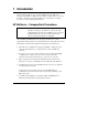
1 Introduction This document describes how to mount an HP NetServer LC 2000 into a Compaq® model 4000- or 7000-series rack. Refer to the HP NetServer LC 2000 Installation Guide that came with the NetServer for instructions on adding accessories to, and configuring the NetServer. HP NetServer – Compaq Rack Precautions CAUTION If this NetServer is not installed according to these instructions, damage to the NetServer or accessories may result.
Chapter 1 Introduction This NetServer is not supported in a rack enclosure under circumstances other than those listed above. See the "Warranty and Support" section of this document for additional support considerations.
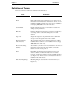
Chapter 1 Introduction Definition of Terms Terms used in this document are defined in the table below. Term Definition Bezel Removable plastic fascia panel that covers entire front of the NetServer. This NetServer includes two bezels: one for installation in HP rack enclosures, and one for installation in Compaq 4000/7000 series rack enclosures. Control Panel Display and buttons used to view NetServer status and change system parameters. EIA unit Industry standard measurement (1.75 inches / 44.
2 Preparing the HP NetServer for Rack-Mounting Introduction This chapter describes how to remove the top cover and the pedestal from the HP NetServer LC. WARNING Before removing the top cover, shut down the operating system and disconnect the power cords and unplug telephone cables. Disconnect the power cords to avoid exposure to high energy levels that may cause burns when parts are short-circuited by metal objects, such as tools or jewelry.
Chapter 2 Prepare the HP NetServer for Rack-Mounting Removing the HP NetServer’s Top Cover and Pedestal Use this procedure to remove the bezel, top cover, and pedestal from the pedestal version of the HP NetServer LC 2000. WARNING Do not operate the HP NetServer with its covers removed. Always disconnect the power cord before removing any covers, to avoid exposure to high energy levels that may cause burns when parts are short-circuited by metal objects such as tools or jewelry.
Chapter 2 Prepare the HP NetServer for Rack-Mounting Removing the Bezel 1. Pull the top of the bezel forward until it unsnaps. 2. Lift the entire bezel upward and away from the chassis. See Figure 2-1. The bezel connects to the front of the HP NetServer chassis with two snap-in connectors at the top front of the chassis and two metal tabs, which fit into two slots on the bottom front of the chassis. Figure 2-1.
Chapter 2 Prepare the HP NetServer for Rack-Mounting Removing the Top Cover 1. Remove the single screw that secures the top cover to the front of the NetServer. 2. Slide the top cover forward to disengage the mounting brackets. 3. Lift the top cover off (See Figure 2-2). Top Cover Screw Hole Figure 2-2.
Chapter 2 Prepare the HP NetServer for Rack-Mounting Removing the Pedestal The pedestal version of the HP NetServer LC 2000 mounts to an anti-tip pedestal, which must be removed to mount the server in a rack. NOTE The front bezel is shown removed, but the bezel may remain on the chassis while removing the pedestal. 1. Disconnect all cables connected to the rear of the NetServer that would limit its rotation before continuing. 2.
3 Rack-Mounting the HP NetServer This chapter explains how to mount the HP NetServer in a Compaq model 4000- or 7000-series rack enclosure. Figure 3-1 shows a Compaq model 4000- or 7000-series rack. Side Stabilizing "Feet" (Both Sides) Front Stabilizing "Feet" Figure 3-1.
Chapter 3 Rack-Mounting the HP NetServer The HP NetServer rack mount kit requires five EIA units of space in the rack. Before mounting the NetServer, plan the NetServer’s location in the rack relative to other rack components. Proper placement is vital both for safety and operating efficiency. For more details, see the HP Rack Installation Road Map and the HP NetServer LC 2000r Rack Cabling Reference Guide.
Chapter 3 Rack-Mounting the HP NetServer Preparing the Rack The column adapters and cage nuts must be connected to the rack before mounting the slide mechanism. Once the slides are correctly mounted, then the HP NetServer LC 2000r can be installing into the rack. HP NetServer Rack Mount Parts List Ensure the rack-mounting kit provided with the HP NetServer and the non-HP rack mount kit contain the following parts. Table 2-1.
Chapter 3 Rack-Mounting the HP NetServer 1. Use the marking pen to mark the 2nd and 14th holes on both front columns, as shown on the template. See Figure 3-2. The two column adapters are mounted at the 2nd and 14th holes on the respective front column and provide the captive nuts for mounting the rack slides to the front columns at 7th and 9th holes from the bottom. If you don’t have the template, Figure 3-2 shows the location on the front columns for the column adapters.
Chapter 3 Rack-Mounting the HP NetServer "#" represents the EIA unit numbers on the rack columns. # # # 9th Hole From Bottom # 7th Hole From Bottom # Bottom of Compaq Rack Figure 3-4. Cage Nut Locations on the Rack’s Rear Columns Attaching the Column Adapters and Slides 1. Make sure that anti-tip precautions have been taken before installing servers in the rack. 2. Align the right column adapter to the right front column. 3.
Chapter 3 Rack-Mounting the HP NetServer Slide Mount Left Column Adapter Front Column Adapter Bottom of HP NetServer Figure 3-5. Mounting Column Adapter to Front Columns 6. Reposition the front brackets on the slides. See Figure 3-6. a. Remove the nuts from the two front slide screws. . b. Move the slide outward into the next set of holes. c. Replace and tighten the nuts.
Chapter 3 Rack-Mounting the HP NetServer Front Figure 3-6. Repositioning the Front Bracket 7. Reposition the rear brackets on the slides. See Figure 3-7. a. Loosen the nuts on the two front slide screws. . b. Move the slide outward to the outer end of the slot. Rear Figure 3-7.
Chapter 3 Rack-Mounting the HP NetServer 8. Hold a slide in position inside the two left-hand rack columns and observing the following items. a. The mounting flange on each end of the slide must wrap around the outside face of both the front and rear columns. See Figure 3-8. b. The two holes in the mounting flange should line up with the captive nuts (at 7th and 9th holes) in the column adapter and the two cage nuts you installed on each rear column. c.
Chapter 3 Rack-Mounting the HP NetServer 9. With the slide pushed firmly into position, insert two screws through the slide’s front bracket into the captive nuts on the left column adapter. a. Use the dimple in the bracket to position the slides in the proper location. b. Then tighten the screws until the bracket is held firmly to the column adapter and rack column. See Figures 3-5 and 3-8. 10. Fasten the slide’s rear bracket to the cage nuts on the left-rear column. a.
Chapter 3 Rack-Mounting the HP NetServer 4. Install and tighten the two Phillips screws as shown in Figure 3-9. Follow steps 3 and 4 to attach the catch mechanism on the right side of the LC 2000. Figure 3-9.
Chapter 3 Rack-Mounting the HP NetServer Attaching the Mounting Handles Attach the four sheet metal mounting handles to the sides of the server. Each handle requires two Phillips head screws. See Figure 3-10. Figure 3-10. Attaching the Mounting Handles Placing the HP NetServer in the Rack Use this procedure to position the HP NetServer into the extended slides and secure the chassis to the slides. Once the NetServer is in the rack, then you connect the Cable Management Arm to the rear of the NetServer.
Chapter 3 Rack-Mounting the HP NetServer WARNING The HP NetServer weighs 80 lbs. (36 kg) fully loaded. To prevent an accident, use two people when placing the NetServer into the rack. Mounting Tabs Stabilizing Feet Figure 3-11. Pulling Out the Slides 3. Pull out both slides until the slide members are fully extended. See Figure 3-11. The slides click into position when locked.
Chapter 3 Rack-Mounting the HP NetServer 6. Position the NetServer’s channels on each side to insert the slide members into the channels. See Figure 3-12. The mounting tabs in the slides will engage the slots in the chassis. See Figure 3-13. Channel(2) Figure 3-12. Mounting the HP NetServer on the Slides 7. Lower the NetServer onto the slide members. See Figure 3-12. The handles will temporarily support the NetServer on the slides.
Chapter 3 Rack-Mounting the HP NetServer 8. Adjust the NetServer’s position on the slide members to line up the mounting holes on each side (3 each) of the chassis with the screw holes in the slide members. Figure 3-13. Removing the Mounting Handles 9. Insert the flathead screws into the slides’ holes at the rear and the panheads screws in the other four places to secure the chassis to the slides. 10. Use a T-15 Torx driver to remove the screws holding the handles to the NetServer. See Figure 3-13. 11.
Chapter 3 Rack-Mounting the HP NetServer The handles can be re-attached whenever you remove the NetServer from the rack. If moving the NetServer elsewhere, always package it with the handles attached. 12. Press in the release latches on each slide, and push the NetServer all the way into the rack. See Figure 3-14. The blue Slide Release buttons in the Bezel moldings on each side of chassis’s front edge must click into the latches in the column adapters on the two front rack columns. Figure 3-14.
Chapter 3 Rack-Mounting the HP NetServer Attaching the Cable Management Arm Use this procedure to mount the Cable Management Arm on the HP NetServer LC 2000r when mounted in the HP System/E or System /U racks. The HP NetServer LC 2000r’s Cable Management Arm allows the cables, including the power cord, to move in and out with the HP NetServer chassis without any damage or being accidentally disconnected. See Figure 3-16.
Chapter 3 Rack-Mounting the HP NetServer Rear of HP NetServer Left Rear Rack Column Cable Management Arm Figure 3-16. Attaching the Cable Management Arm 5. Attach the other flange of the cable arm to the rear column of the rack with the two M6 screws, included with the non-HP rack kit. 6. Attach the flange to the NetServer with the two 2-32 pan head Torx T-20 screws, included with the Arm. See Figure 3-16. 7.
Chapter 3 Rack-Mounting the HP NetServer 10. Plug the HP NetServer’s power cable and all available data cables into the back of the NetServer. Attaching the Front Bezel Adapter The front bezel adapter fits the front bezel properly in the Comaq rack. Attach the front bezel adapter by pushing the connectors on the adapter into the corrosponding holes on the front bezel as shown in Figure 3-17. Front Bezel Adapter Figure 3-17.
Chapter 3 Rack-Mounting the HP NetServer Attaching the Front Bezel The front bezel attaches to the HP NetServer by a hinge on the left and a catch on the right. The hinge has three spring loaded hinge pins to secure the bezel. The bezel is held in place on the right with a catch allowing the bezel to swing open when pulled from the right. The chassis is shipped with the bezel hinge and latch in place.
Chapter 3 Rack-Mounting the HP NetServer 2. Press down on the blue Bezel Release Tab shown in Figure 3-19. Figure 3-19. Attaching the Bezel to the NetServer 3. Press the bezel onto the front of the HP NetServer and release the Blue Tab to engage the hinge pins. See Figures 3-18 and 3-19. 4. Swing the open bezel to the right to engage the catch and close the bezel.
4 Warranty and Support The hardware warranty below applies to components purchased as accessories. If your component was factory installed as part of an HP NetServer model, refer to the HP NetServer Warranty and Service/Support Booklet provided with your system documentation for the warranty limitations, customer responsibilities, and other terms and conditions.
Chapter 4 Warranty and Support HP Repair and Telephone Support Refer to the HP NetServer Warranty and Service/Support Booklet supplied with your HP NetServer system documentation for instructions on how to obtain HP repair and telephone support.
Index Cable management arm, attaching, 26 Cage nuts, attaching, 13 Column adapters and slides, attaching, 15 Definition of Terms, 4 Front bezel adapter, attachment, 28 Front bezel attachment, 29 Hinge and catch assemblies, attaching, 19 HP NetServer rack installation, 21 HP NetServer rack-mounting preparation, 5 Mounting handles, attaching, 21 Precautions, Compaq rack, 1 Precautions, safety, 2 Rack Mount Parts List, 13 Rack Mounting the HP NetServer, 11 Removing Bezel, 7 Removing Pedestal, 9 Removing Top C