HP NetServer LH 4r Rack Cabling Reference HP Part Number D6969-90005 Printed in November 1998
Notice The information contained in this document is subject to change without notice. Hewlett-Packard makes no warranty of any kind with regard to this material, including, but not limited to, the implied warranties of merchantability and fitness for a particular purpose. Hewlett-Packard shall not be liable for errors contained herein or for incidental or consequential damages in connection with the furnishing, performance, or use of this material.
Contents 1 About This Cabling Reference .................................................................... 1 Introduction ................................................................................................... 1 Before You Use This Reference ................................................................ 1 Purpose of This Document ........................................................................ 1 Building an HP NetServer Rack............................................................
Contents Cabling Two Power Supplies and High Density Configuration Examples . 38 Cable Routing: Creating the Cable Management Loop ................................ 41 Power Up the Components in the Rack ....................................................... 42 Power Up Sequence................................................................................ 42 Power Down Considerations.................................................................... 43 3 Cabling Reference Information ...................
1 About This Cabling Reference Introduction Before You Use This Reference This cabling reference assumes that you have the rack assembly process completed, have mounted the HP NetServer LH 4r, and are ready to cable the components in the rack enclosure. For instructions on how to install the HP NetServer LH 4r in a rack, consult the installation guide or user guide shipped with your unit.
Chapter 1 About This Cabling Reference Building an HP NetServer Rack Suggested Method for Building an HP NetServer Rack Installation 1.
Chapter 1 3. About This Cabling Reference Prepare Rack Enclosures for Assembly WARNING A tip-over hazard exists. Rack enclosures are shipped upright and are top-heavy. Never move enclosures without adequate equipment and assistance. Use caution to prevent rack from falling over and causing potential damage or injury. If you receive pre-configured units, follow assembly instructions from the supplying organization first, if you have them. Otherwise, continue with this set of instructions.
Chapter 1 About This Cabling Reference WARNING When equipment is mounted on slides, a tip-over hazard exists. Always take the precautions listed below: Extend or bolt on the anti-tip foot for each rack before mounting equipment on slides. Never extend more than one piece of equipment on slides at time. Reduce weight by removing power supplies and hard disk modules from servers. Always use the rack mounting handles that are shipped on rack optimized units as shown in accompanying instructions. 4.
Chapter 1 NOTE About This Cabling Reference HP Rack System product numbers J1487B, J1487B option AXH, and J1488A require that enclosures to be tied together before any components are mounted inside them. To avoid problems, if these rack versions are to be tied together, do so before installing slide members, rails, shelves, units, or other hardware. Otherwise, you may have to remove components from the rack to gain access to the tie-bolt locations. 2.
Chapter 1 5. About This Cabling Reference Mount Component in the Rack Plan Component Locations Use the original ordering information to locate where each component goes in the rack. If the original ordering information is not available, use HP rack configuration tools to plan the location of each component. You can also use the HP NetServer rack configuration tools (for instance, HP Rack Assistant) to make ordering easier and to automatically check that orders are complete.
Chapter 1 About This Cabling Reference 4. Be sure to locate and place rack nuts along the front outside face of the vertical column before placing each component on its rails or base. The pre-positioning of rack nuts allows the front of the component to be secured to the front of the rack. (Some units use threaded inserts or bar nuts, and require no rack nuts to secure the unit to the rack.) 5. Mount each unit on its accompanying rails, brackets, or slides. CAUTION Tip-over hazard exists.
Chapter 1 About This Cabling Reference • Create a cable management loop by providing sufficient cable length to allow servers to be extended from the rack for maintenance. • Attach data cables to their respective components. Attach power cables • Connect each component to a Power Distribution Unit (PDU) or Units. • Connect PDU and Uninterruptible Power Supply (UPS)--if present--cables to Branch Circuits. Route and tie cables • Route cables through cable guide and tie wrap them in place.
Chapter 1 About This Cabling Reference Prevent Electric Shock WARNING Ensure site electrical circuits have reliable earth grounding. Never operate products in any rack enclosure with the ground connector disconnected. Although leakage current from any one device may be minimal, cumulative leakage current of equipment mounted in a rack may exceed 5mA, and could reach 15mA. This level of current can be dangerous, unless a reliable earth ground is in place.
2 Connecting and Routing Cables to the HP NetServer LH 4r Introduction Overview of Cabling Steps This chapter includes information on cabling the server and other components in a rack, including: • Site preparation • Cabling preparation for data and power • Attach data cables • Attach power cables • Cable routing and management • Power on the equipment in the rack The HP NetServer LH 4r This cabling reference is for the rack optimized HP NetServer LH 4r shown in Figure 2-1.
Chapter 2 Connecting and Routing Cables to the HP NetServer LH 4r Figure 2-1. The Rack Optimized HP NetServer LH 4r Site Preparation You may want to copy and use the site preparation checklist in this section with a representative of the organization installing the rack. Doing so before you begin may reveal actions you can take to support your success.
Chapter 2 Connecting and Routing Cables to the HP NetServer LH 4r Site Preparation Checklist Table 2-1. Site Preparation Checklist HP NetServer Customer Responsibilities Logical and physical network design provided. Server configuration parameters determined. Disk partition and directory structure determined. Required incoming power and data cabling in place. Working LAN, one working client, one working printer available (if integrating into an existing network). Software license requirements met.
Chapter 2 Connecting and Routing Cables to the HP NetServer LH 4r Table 2-1. Site Preparation Checklist (Continued) Environment and Space Requirements In the United States, must meet OSHA code. Elsewhere, must meet local code and HP specifications for safety and supportability. (A 3-foot--90 cm--minimum access in front and rear of electrical cabinets is required.) Side access of 24 inches (60 cm) improves cable routing and management. 24 hour air conditioning (68 - 72 deg. F; 20 - 22 deg. C, 40 - 60% RH).
Chapter 2 Connecting and Routing Cables to the HP NetServer LH 4r Site Preparation: Circuit Breakers When you connect the HP NetServer LH 4r to an AC power source, the server temporarily draws a large "inrush current. " This occurs even when the system is in standby mode. Inrush current is much greater than the server’s normal operating needs. Generally, your external AC power source can handle the inrush current. If you install several HP NetServers on one circuit, however, precautions are necessary.
Chapter 2 Connecting and Routing Cables to the HP NetServer LH 4r Cabling Preparation for the HP NetServer LH 4r Assess How Components Will Be Connected to the Server You may find the following steps helpful before you begin cabling. • Review the layout of the rack installation generated with HP’s rack configuration tools. (See Step 2 in Chapter 1 for more information.) • Consider the cabling guidelines discussed in Chapter 3, in the section "Data Cabling Principles Used in Determining Rack Locations.
Chapter 2 Connecting and Routing Cables to the HP NetServer LH 4r Three Types of Power Distribution Unit The three types of Power Distribution Units (PDU) currently available for the LH 4r are: ◊ The 120 VAC PDU (HP product number E7675A) is designed to fit horizontally between the columns of the rack, but can also be mounted vertically along the outside edge of the vertical column. See Figure 2-2.
Chapter 2 Connecting and Routing Cables to the HP NetServer LH 4r Table 2-2.
Chapter 2 Connecting and Routing Cables to the HP NetServer LH 4r Figure 2-2. Three PDU Configurations The 208-240 VAC, wide-voltage-range-rated, switchless version of the Power Distribution Unit (PDU) can be mounted in several configurations with the LH 4r. One of these configurations is shown in Figure 2-3 below. Others are listed in Table 3-2 and discussed in Chapter 3. Placement limitations for the PDU are shown in Table 2-2.
Chapter 2 Connecting and Routing Cables to the HP NetServer LH 4r Figure 2-3. Mounting a Pair of PDUs Horizontally (Rear View) Once you have determined the general location and orientation, install the PDUs for the rack as described below: Mounting the PDU Horizontally Installation Steps To mount a PDU horizontally, follow these steps: 1. Determine the exact location of the PDU. A PDU is not recommended behind certain HP units, as shown in Table 2-2.
Chapter 2 Connecting and Routing Cables to the HP NetServer LH 4r NOTE As shown in Table 2-2, if you locate the PDU behind the HP NetServer LH 4r, HP Rack Storage/12, HP Rack Storage/8 or HP NetServer LH 3r, then the hot-swappable power supplies (or sometimes the fans) designed for access and replacement from the rear of the rack will not be easily accessible.
Chapter 2 Connecting and Routing Cables to the HP NetServer LH 4r CAUTION Orient the star-washer on the hex nut toward the painted surface of the rack. Tighten the screw and nut sufficiently to cause the star washers to pierce the paint and bring the lock washer teeth in contact with metal. This ensures that the rack-to-ground connection to the PDU is made.
Chapter 2 Connecting and Routing Cables to the HP NetServer LH 4r 2. Use the row of mounting holes nearest the outside edge of the vertical column. Use the hex nut and screw supplied with the PDU. Hold the nut behind the column and insert the screw through the top mounting bracket of the PDU, and through the face of the vertical column. Start it in the nut (see Figure 2-5). 3. Insert a screw through the other mounting bracket of the PDU, through the vertical column, and into a nut. Tighten both screws.
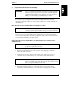
Chapter 2 Connecting and Routing Cables to the HP NetServer LH 4r Figure 2-6 shows the connections of the mouse, video, and keyboard cables from the devices through the HP Console Switch, to the server. Alternate cabling paths for SCSI cables from the server to the mass storage units are also shown. Figure 2-6. Overview of Data Cabling of the HP NetServer LH 4r NOTE Figure 2-6 shows an HP Console Switch, which is not necessary for configuring the system, but is shown for informational purposes.
Chapter 2 Connecting and Routing Cables to the HP NetServer LH 4r 4. Attach the video cable to the video port on the server. Attach the mouse and keyboard cables to the server. If you are using one keyboard, mouse, and monitor for more than one server, attach the cables for the HP Console Switch to the server ports of the video card and the mouse and monitor ports.
Chapter 2 Connecting and Routing Cables to the HP NetServer LH 4r Attach Power Cables When all components have been mounted in the rack and their data cables connected the power cables can be attached. Attaching Server and Component Power Cables 1. Make sure all power switches (for devices which have switches) are in the "off" position. "Off" is indicated by a circle, "on" is indicated by a straight line. 2. Attach the power cords for each device.
Chapter 2 Connecting and Routing Cables to the HP NetServer LH 4r Determining Current Draw on Two Circuits in One Rack NOTE Amperage ratings for use in determining loads on the Power Distribution Unit are shown in Tables 3-4, 3-5, 3-6, and 3-7. If applicable, use two circuits (each including a Power Distribution Unit and an optional Uninterruptible Power Supply) in one rack. Attempt to balance the current drawn through each circuit.
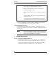
Chapter 2 Connecting and Routing Cables to the HP NetServer LH 4r Figure 2-7. Power Connection Locations on a Typical Rack (Rear View) Power Considerations for the HP NetServer LH 4r The HP NetServer LH 4r can be configured in systems with any of four voltage ranges: 100, 120, 200/208, or 230/240/250 VAC. Power supply (UPS) and distribution (PDU) components are available to support all three configurations.
Chapter 2 Connecting and Routing Cables to the HP NetServer LH 4r ◊ For 120 VAC, a 16-amp Power Distribution Unit (PDU) is available ◊ For both 200/208 and 230/240 voltages, two Power Distribution Unit (PDU) models (rated 10 A and 16 A) are available ◊ Multiple PDUs can be used in each rack enclosure, depending upon requirements for power, current, and number of receptacles ◊ The appropriate power cord for each server is shipped according to local requirements; refer to Table 3-1 for details 100/1
Chapter 2 Connecting and Routing Cables to the HP NetServer LH 4r If you use a wall socket directly without a UPS or PDU, be sure to check power requirements against the amperage rating of your electrical system. See the section titled "Site Preparation: Circuit Breakers. " If your electrical system has the capacity to power the components, plug the HP NetServer LH 4r and mass data storage units into NEMA 5-15 receptacles using the 90-inch (approximately 230 cm) power cords supplied. Table 2-3.
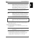
Chapter 2 Connecting and Routing Cables to the HP NetServer LH 4r Figure 2-8. PDU 120 VAC Configuration Figure 2-8 shows a UPS connected to the power grid through a captive cord with a NEMA 5-20P. The UPS has receptacles for use in the rack: two (on the right rear) NEMA 5-20R and six NEMA 5-15R. The PDU connects to the UPS via a detachable cord (NEMA 5-20P to an IEC 320 C20). The 120 VAC PDU has nine NEMA 5-15R and one (at the right) IEC 320 receptacle.
Chapter 2 Connecting and Routing Cables to the HP NetServer LH 4r Two 120 V PDUs per UPS Possible Two 120 VAC PDUs can be plugged into the UPS in this 120 V power configuration. There are also six NEMA 5-15R receptacles in the standard UPS which can be used for equipment in the same rack if needed. 200/208V PDU Rack Power Configurations The 208 VAC PDU power configurations appear as shown below in Table 2-5 and Figure 2-9.
Chapter 2 Connecting and Routing Cables to the HP NetServer LH 4r Table 2-5. 200/208 VAC PDU Power and Current Component (Note 1, 2) Model Input Power (VA) Input Power (W) Current (A) 200/208 VAC PDU E7671A or E7672A N/A N/A maximum 16 HP NetServer LH 4r D7093A (400 MHz/512) D7095A (400/1M) D6970A (450 MHz/512) D6972A (450 MHz/1M) 1130 1100 5.7 HP NetServer Rack Storage/12 D5989A 548 537 2.6 HP NetServer Rack Storage/8 D4902A 211 209 1.1 HP Console Switch J1497A 42 29 0.
Chapter 2 Connecting and Routing Cables to the HP NetServer LH 4r Figure 2-9.
Chapter 2 Connecting and Routing Cables to the HP NetServer LH 4r 230/240V PDU Rack Power Configurations Configurations for the 230/240 VAC, PDU options are shown in the text below, Table 2-6, and Figure 2-10. 230/240 VAC Power Configuration In a country with a 230/240 VAC power system, the high-voltage (230/240 V) PDU model E7671A is required.
Chapter 2 Connecting and Routing Cables to the HP NetServer LH 4r Table 2-6. 230/240 VAC PDU Power and Current Component (Note 1, 2) Model Input Power (VA) Input Power (W) Current (A) 230/240 VAC PDU E7671A or E7672A N/A N/A maximum 16 HP NetServer LH 4r D7093A (400 MHz/512) D7095A (400/1M) D6970A (450 MHz/512) D6972A (450 MHz/1M) 1120 1100 4.9 HP NetServer Rack Storage/12 D5989A 548 537 2.3 HP NetServer Rack Storage/8 D4902A 211 209 0.9 HP Console Switch J1497A 42 29 0.
Chapter 2 Connecting and Routing Cables to the HP NetServer LH 4r Figure 2-10.
Chapter 2 Connecting and Routing Cables to the HP NetServer LH 4r Cabling Two Power Supplies and High Density Configuration Examples Two Sets Powered by Two Supplies A double power supply configuration can be created by ensuring that two different branch circuits to feed two different Uninterruptible Power Supplies, which in turn power two PDUs. Figure 2-11 shows a double power cabling example. This example shows two sets of server-storage units powered by two PDUs and two UPS units. Figure 2-11.
Chapter 2 Connecting and Routing Cables to the HP NetServer LH 4r Power Supply Redundancy and Power Cable Non-Redundancy When two HP NetServer LH 4r units are loaded in a single rack, power supply redundancy is possible. To achieve power supply redundancy, a fourth power supply must be installed in each LH4r. However, there is no power cord redundancy. Therefor, plug both power cords for one unit in to one PDU-UPSbranch circuit.
Chapter 2 Connecting and Routing Cables to the HP NetServer LH 4r Figure 2-12.
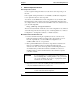
Chapter 2 Connecting and Routing Cables to the HP NetServer LH 4r Cable Routing: Creating the Cable Management Loop A cable management loop allows the NetServer to be extended by service personnel (without disconnecting data cables) for upgrades and maintenance. In a fully utilized HP NetServer LH 4r, you can form a cable management loop by connecting cables when the server is fully extended from the rack. (Be sure to extend the anti-tip foot from the front of the rack before extending the server.
Chapter 2 Connecting and Routing Cables to the HP NetServer LH 4r Figure 2-13. Forming the LH 4r Cable Management Loop Power Up the Components in the Rack Follow the Power Up Sequence to minimize initial surge currents and prevent breakers from tripping. Power Up Sequence 1. Ensure that the mass storage unit DIP switches are set for SCSI ID spinup order. See documentation included with the unit for more information. 2. Power on the tape back-up unit, if one is present. 3.
Chapter 2 Connecting and Routing Cables to the HP NetServer LH 4r 5. If an HP Console Switch is present, it must be on before the server is turned on. Otherwise the server will not detect all the required components, and will likely report an error. 6. Lastly, power on one server at a time, waiting for fan units to spin up before powering on the next (if more than one is present in the rack). Power Down Considerations To power off the equipment, ensure that the network has been properly warned.
3 Cabling Reference Information Power Cords and Component Reference Table 3-1 gives details of the plugs and receptacles for three different power alternatives for use with the HP NetServer LH 4r.
Chapter 3 Cabling Reference Information Table 3-1. LH 4r Plugs and Receptacles Reference Item 100/120VAC 200/208VAC 230/240VAC LH 4r, RS/8 Line Cord 8120-8378 NEMA 5-15 plug, 90" (2.3 m), 16 AWG See next line. See next line. LH 4r, RS/8 PDU Jumper Cord Model No. PDU Model No. Can PDUs be "Daisy Chained"? PDU Linecord style Recommended PDU linecord for installations with recommended UPS See previous line.- E7742A 90 inch (2.3 m) E7742A 90 inch (2.
Chapter 3 Cabling Reference Information Wide-Ranging PDU Configurations Use of four possible 200 - 240 VAC PDU configurations depends upon the power requirements of the devices in the rack. Table 3-1 shows the characteristics used to determine how many PDUs are supplied with each rack configuration. In configurations that use a wide-ranging 10-amp PDU, it will always be plugged into a wide-ranging 16-amp PDU. Table 3-2.
Chapter 3 Cabling Reference Information Table 3-3. Receptacles Needed for Different Units Component Receptacles Required HP NetServer LH 4r two C13 or two 5-15R HP Rack Storage/8 or Rack Storage/12 two C13 or use Y-Cable* All other devices one C13 * Two Y-Cables may be used to connect two HP Rack Storage/8 units to two C13 receptacles. 3.
Chapter 3 Cabling Reference Information Power and Current for Estimating Supply Needs Table 3-4. 100 VAC Power and Current: Approximate Current Requirements of Rack Optimized Devices and Components Device (Notes 1, 2, 3) HP NetServer LPr HP NetServer LXr 8000 HP NetServer LH 4r HP NetServer LH 3r HP NetServer LXr Pro8 HP NetServer LXr Pro HP Rack Storage/12 HP Rack Storage/8 Monitor (14-inch.) Monitor (15-21-inch.
Chapter 3 Cabling Reference Information Table 3-5. 120 VAC Power and Current: Approximate Current Requirements of Rack Optimized Devices and Components Device (Notes 1, 2, 3) HP NetServer LPr HP NetServer LXr 8000 HP NetServer LH 4r HP NetServer LH 3r HP NetServer LXr Pro8 HP NetServer LXr Pro HP Rack Storage/12 HP Rack Storage/8 Monitor (14-inch.) Monitor (15-21-inch.
Chapter 3 Cabling Reference Information Table 3-6. 200/208 VAC Power and Current: Approximate Current Requirements of Rack Optimized Devices and Components Device (Notes 1, 2, 3) HP NetServer LPr HP NetServer LXr 8000 HP NetServer LH 4r HP NetServer LH 3r HP NetServer LXr Pro8 HP NetServer LXr Pro HP Rack Storage/12 HP Rack Storage/8 Monitor (14-inch.) Monitor (15-21-inch.
Chapter 3 Cabling Reference Information Table 3-7. 230/240 VAC Power and Current: Approximate Current Requirements of Rack Optimized Devices and Components Device (Notes 1, 2, 3) HP NetServer LPr HP NetServer LXr 8000 HP NetServer LH 4r HP NetServer LH 3r HP NetServer LXr Pro8 HP NetServer LXr Pro HP Rack Storage/12 HP Rack Storage/8 Monitor (14-inch.) Monitor (15-21-inch.
Chapter 3 Cabling Reference Information Data Cabling Principles Used in Determining Rack Locations A series of positioning rules are used in the HP rack configuration tools to help determine where each component is placed in multiple rack layouts. Key Cabling Guidelines Used in Developing a Rack Layout The following discussion is intended to support your understanding of how your rack order was arrived at. It also discusses how rack layouts affect the attachment and routing of cables.
Chapter 3 Cabling Reference Information • Cable guide placement is determined in turn by where the doors are hinged. Doors can be mounted to swing from either side of the rack. Locate the cable guide on the same side of the rack as the door hinge hardware. Locate the PDU opposite the cable guide (if mounted vertically), on the same side as the door latch hardware. If mounted horizontally, PDU location does not make a significant difference to cable routing.
Index A air flow in the rack, 54 assembly instructions where to find, 1 assumptions, 1 audience, 1 C Cable Guide installation, 16 placement not recommended table, 18 where to mount, 16 cable management forming a cable management loop, 42 how to attach the Cable Guide, 16 planning for, 53 power cords within occupied area, 26 power cords within same EIA unit, 26 cable management loop how to form, 42 how to form for the LH 4r, 41 cable routing cabling guidelines for the LH 4r, 23 guidelines for server and stor
Index M multiple rack bays tie together kit, 4 O overview cabling the assembled rack, 7 data cabling, 23 P PDU.
Index extend one unit at a time, 4 leveler feet, 3 lifting precautions, 3 minimize server weight, 7 moving racks safely, 3 prevent tip-over, 6 preventing component damage, 9 rack cabling, 8 rear latch removal, 5 remove power supplies and disk packs, 4 use attached rack mounting handles, 4 SCSI cables illustration of LH 4r connections, 24 shipment to a second location packaging materials, 2 remove and save shipping panels, 4 side panels removal of, 5 site preparation, 12 checklist, 13 circuit breakers, 15