HP NetServer LT 6000r Rack Cabling Reference Guide HP Part Number D9143-90008 Printed February 2000
Notice The information contained in this document is subject to change without notice. Hewlett-Packard makes no warranty of any kind with regard to this material, including, but not limited to, the implied warranties of merchantability and fitness for a particular purpose. Hewlett-Packard shall not be liable for errors contained herein or for incidental or consequential damages in connection with the furnishing, performance, or use of this material.
Contents 1 Preparation for Cabling the NetServer LT 6000r ........................................ 1 About Cabling the LT 6000r ........................................................................... 1 Before You Use this Reference Guide ....................................................... 1 The HP NetServer LT 6000r ...................................................................... 1 Site Preparation.............................................................................................
Contents Overview of LT 6000r Data Connections.................................................. 34 Attach Data Cables to the Server............................................................. 38 Attach Data Cables to Other Components ............................................... 40 Step 3: Cable the LT 6000r for Power .......................................................... 40 Attaching Server and Component Power Cables......................................
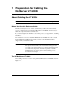
1 Preparation for Cabling the NetServer LT 6000r About Cabling the LT 6000r NOTE A checklist for the cabling process is included in Appendix A. Before You Use this Reference Guide This Rack Cabling Reference Guide assumes that you have the rack assembly process completed, have mounted the HP NetServer LT 6000r, and are ready to cable the components in the rack enclosure. If you want a high-level checklist to use in this process, see Appendix A, "Cabling Checklist.
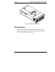
Chapter 1 Preparation for Cabling the HP NetServer LT 6000r Figure 1-1. The HP NetServer LT 6000r Site Preparation You may want to copy and use the site preparation checklist in this section (Table 1-1). Doing so before you begin to install and cable the NetServer may reveal actions you can take to support your success. Also be sure to read the section on site preparation of circuit breakers.
Chapter 1 Preparation for Cabling the HP NetServer LT 6000r Site Preparation Checklist Table 1-1.
Chapter 1 Preparation for Cabling the HP NetServer LT 6000r Table 1-1. Site Preparation Checklist (Continued) Environment and Space Requirements Must meet OSHA, local code, and HP specifications for safety and supportability (3 feet minimum access in front and rear of electrical cabinets) Side access of 24 inches improves cable routing and management Optimal: 24 hour air conditioning (68 - 72 deg. F; 20 - 22 deg.
Chapter 1 Preparation for Cabling the HP NetServer LT 6000r Site Preparation -- Circuit Breakers When you connect the HP NetServer LT 6000r to an AC power source, the server temporarily draws a large “inrush current.” This occurs even when the system is in standby mode. Inrush current is much greater than the server’s normal operating needs. Generally, your external AC power source can handle the inrush current. However, if you install several HP NetServers on one circuit, precautions are necessary.
Chapter 1 Preparation for Cabling the HP NetServer LT 6000r Prevent Electrical Shock WARNING Ensure site electrical circuits have reliable earth grounding. Never operate products in any rack enclosure with the ground connector disconnected. Although leakage current from any one device may be minimal, cumulative leakage current of equipment mounted in a rack may exceed 5mA, and could reach 15mA. This level of current can be dangerous, unless a reliable earth ground is in place.
Chapter 1 Preparation for Cabling the HP NetServer LT 6000r Generic Rack Assembly Steps Suggested Method for Building an HP NetServer Rack Installation 1.
Chapter 1 Preparation for Cabling the HP NetServer LT 6000r If you receive pre-configured units, follow assembly instructions from the supplying organization first, if you have them. Otherwise, continue with this set of instructions. 4. Move Rack Enclosures and Other Units to Installation Location WARNING Whenever you lift equipment, limit the amount of weight each person picks up. Lift with your legs, not with your back.
Chapter 1 Preparation for Cabling the HP NetServer LT 6000r 4. Remove shipping panels, if present, from inside the rack enclosure. Save panels, screws, and rack nuts if you are going to reship the rack. 6. Unpack Remaining Components Unpack each component in the order in which you assemble them (from the bottom of the rack upward). Each package contains rack installation instructions or a user guide. NOTE If an Uninterruptible Power Supply (UPS) is included, plug it in as soon as you unbox it.
Chapter 1 Preparation for Cabling the HP NetServer LT 6000r WARNING When the back door of a rack is removed, the hinge and latch catch brackets protrude. To avoid injury, temporarily remove these brackets prior to installing components into the rear of the rack. 3. If present, remove side panels to allow better access. Follow instructions included with the rack to do so. 8. Install Fans If Required and Redundant Switch and UPS First If You Have Them 1.
Chapter 1 Preparation for Cabling the HP NetServer LT 6000r Mount Each Unit in the Rack Enclosure 1. Position each unit following the original layout used to order the server. Follow the instructions which accompany each component. If you do not have the original layout, you can use HP rack configuration tools, available at HP’s web site, to regenerate it. 2.
Chapter 1 Preparation for Cabling the HP NetServer LT 6000r When each component is correctly secured in the rack, replace disk drives and power supplies and add the front panel (bezel) to the unit. 6. Proceed with units one by one, from the bottom of the rack to the top. Fill any gaps with filler panels. 10.
Chapter 1 Preparation for Cabling the HP NetServer LT 6000r Managing and Routing Cables • Route cables through the Cable Management Arm and tie-wrap them in place. • Route cables through Cable Guide and tie wrap them in place. Powering Up and Powering Down the Components in the Rack • Follow the power up sequence. See "Power Up Sequence" in Chapter 3. • If it becomes necessary to bring the server power down, follow the "Power Down Considerations" in Chapter 3. 11.
2 Rack Cabling References Rack Configuration Tools Selected reference material derived from HP’s rack configuration tools is published in this chapter for convenience including the following: • necessary and optional components • rack power subsystem configuration and placement • current and power requirements • discussion of component location in the rack • routing cables through the Cable Management Arm and Cable Guide • cooling requirements and air flow HP rack configuration tools are available on the w
Chapter 2 Rack Cabling References Figure 2-1. Three-way Cord to Allow Single Power Input Power Considerations for the HP NetServer LT 6000r The HP NetServer LT 6000r can be configured in a wide range of voltages from 100 - 240 VAC. Power supply (UPS) and distribution (PDU) components are available to support these configurations. A Redundant Switch is also available.
Chapter 2 Rack Cabling References ◊ one or more PDUs can be used in each rack enclosure, depending upon requirements for power, current, and number of receptacles (see Table 2-4) Power Cables and Components Available When components are installed in a rack, a power supply subsystem for the rack is required.
Chapter 2 Rack Cabling References Table 2-1. UPS Models and Power Ratings Uninterruptible Power Supplies Voltage Power (VA)1 Power (Watts)2 NS3000RM3U 100/200 VAC 3000 2250 NS2200RM3U 100/120 VAC3 2200 1600 NS3000RMT3U 200/208 VAC 3000 2250 NS2200RMI3U 230/240 VAC 2200 1600 NS3000RMI3U 230/240 VAC 3000 2250 APC Model Note 1. Ensure UPS Volt Amps rating is not exceeded. Add power in Volt Amps of each component and connect no more than those the UPS supports. Note 2.
Chapter 2 Rack Cabling References Table 2-2. LT 6000r Plugs and Receptacles Reference 100/120 VAC 200/208 VAC 230/240V LT 6000r Jumper Cord 8120-8378 NEMA 5-15 plug, 90" (2.3 m), 16 AWG included C13 to C14, 2.5 m included C13 to C14, 2.5 m RackStorage/12 /12FC and PDU Jumper Cord E7742A, 90 inch (2.5 m), C13 to C14 E7742A, 90 inch (2.5 m), C13 to C14 E7742A, 90 inch (2.5 m), C13 to C14 PDU Model No.
Chapter 2 Rack Cabling References Notes to Table 2-2. Note 1. For 100 VAC Systems, separately orderable cables and UPS are available from American Power Conversion Corporation (APC). Note 2. Consult American Power Conversion Corporation for model number of 100 VAC unit. Note 3. For 100 VAC, consult local electrical codes and order a PDU power cord with appropriate connector from American Power Conversion Corporation (APC). Note 4.
Chapter 2 NOTE Rack Cabling References The extension PDU (E7670A) only increases the number of available receptacles. The total current carrying capacity still is limited to 16 amps for the two PDUs, when daisy chained. In addition, the extension PDU is limited to carrying only 10 amps. Placement of PDU To determine where the PDU mounts, eliminate positions directly behind equipment listed in Table 2-3. (PDUs conflict with these units when mounted in the same space).
Chapter 2 Rack Cabling References Power Distribution Unit Types 200/240 VAC Wide Range, 10-Amp together with 16-Amp and Jumper Cord Available as E7672A 100/120 VAC, 16-Amp, Order as E7675A (Not used with 200/240 VAC models) 200/240 VAC, 16-Amp, Wide Range, Order Standalone as E7671A, Power Cord Separately Orderable Figure 2-2. PDU Configurations The 200/240 VAC, wide-range Power Distribution Unit (PDU) can be mounted in several configurations with the LT 6000r.
Chapter 2 Rack Cabling References How to Position the PDU Count the receptacles needed for each unit in the rack, notice where the PDUs can be most conveniently located, and decide whether to orient the PDU vertically or horizontally.
Chapter 2 Rack Cabling References Guidelines for Powering the LT 6000r in a Rack Four Possible 200/240 VAC Wide Range PDU Configurations Use of four possible 200/240 VAC PDU configurations depends upon the power requirements of the devices in the rack. Table 2-4 shows how to determine how many PDUs are supplied with each rack configuration. In configurations that use a wide-ranging 10-amp PDU, it will always be plugged into a wide ranging 16-amp PDU. Table 2-4.
Chapter 2 Rack Cabling References In this case, use the Y-cable to connect HP Rack Storage/12 or Rack Storage/12FC units to the PDUs. (b) When required, a pair of Y-cables are supplied per pair of Rack Storage/12 or Rack Storage/12FC units. That is, two Y-cables are supplied for two units. (c) Each Y cable connects either the two right power receptacles or the two left power receptacles of a pair of HP Rack Storage/12 or Rack Storage/12FC units to one receptacle on the PDU. Table 2-5.
Chapter 2 Rack Cabling References Table 2-6. 100 VAC Power and Current: Approximate Current Requirements of Rack Optimized Devices and Components Device (Notes 1, 2, 3) Input Power (VA) Input Power (W) 100v IRMS (Amps) HP NetServer LC 2000r 545 540 5.5 HP NetServer LH 3000r 833 825 8.3 HP NetServer LH 6000r 1177 1166 11.7 HP NetServer LT 6000r 833 825 8.3 HP NetServer LPr 530 305 5.3 - - Not Supported HP NetServer LH 4r 1170 1140 11.
Chapter 2 Rack Cabling References Table 2-7. 120 VAC Power and Current: Approximate Current Requirements of Rack Optimized Devices and Components Input Power (VA) Input Power (W) 120v IRMS (Amps) HP NetServer LC 2000r 531 525 4.5 HP NetServer LH 3000r 815 806 6.7 HP NetServer LH 6000r 1153 1141 9.5 HP NetServer LT 6000r 815 806 6.7 HP NetServer LPr 552 295 4.6 - - Not Supported HP NetServer LH 4r 1160 1130 9.7 HP NetServer LH 3r 650 626 5.
Chapter 2 Rack Cabling References Table 2-8. 200/208 VAC Power and Current: Approximate Requirements of Rack Optimized Devices and Components Device (Notes 1, 2, 3) Input Power Input Power (VA) (W) 208v IRMS (Amps) HP NetServer LC 2000r 516 506 2.5 HP NetServer LH 3000r 792 777 3.7 HP NetServer LH 6000r 1120 1099 5.3 HP NetServer LT 6000r 792 777 3.7 HP NetServer LPr 640 285 3.2 HP NetServer LXr 8000 and LXr 85004 1121 1077 5.6 HP NetServer LH 4r 1130 1100 5.
Chapter 2 Rack Cabling References Table 2-9. 230/240 VAC Power and Current: Approximate Requirements of Rack Optimized Devices and Components Device (Notes 1, 2, 3) Input Power (VA) Input Power (W) 230/240v IRMS (Amps) HP NetServer LC 2000r 514 504 2.3 HP NetServer LH 3000r 790 774 3.4 HP NetServer LH 6000r 1117 1095 4.8 HP NetServer LT 6000r 790 774 3.4 HP NetServer LPr 644 285 2.8 HP NetServer LXr 8000 and LXr 85004 1121 1077 4.9 HP NetServer LH 4r 1120 1100 4.
Chapter 2 Rack Cabling References Data Cabling References and Guidelines A series of positioning rules is used in the HP rack configuration tools to help determine where each component is placed in multiple rack layouts. Key Cabling Guidelines Used in Developing a Rack Layout The following discussion is intended to support your understanding of how your rack order was arrived at. It also discusses how rack layouts affect the attachment and routing of cables.
Chapter 2 Rack Cabling References • Ensure the monitor cables and mouse cables are long enough to allow the NetServer to be extended at the same time the keyboard tray is pulled out. Use locally available extensions if necessary. • The mounting distances provided in rack configuration tools assume cables between the servers and connected devices provide for the Cable Management Arm (for the LT 6000r).
3 Procedure for Connecting and Routing Cables to the LT 6000r Step 1: Prepare to Cable the HP NetServer LT 6000r Assess How Components Will be Connected to the Server You may find the following steps to be helpful before you begin cabling: • Review the layout of the rack installation generated with Hewlett-Packard rack configuration tools, such as Rack Assistant (available at www.hp.com/go/netservers).
Chapter 3 Procedure for Connecting and Routing Cables to the LT 6000r Mount Power Distribution Units Plan the location of the Power Distribution Unit or Units (PDU) by reference to amperage, power, and the number of receptacles. See Chapter 2, the section entitled "Wide Range PDU Configurations," particularly Table 2-4. Follow mounting instructions included with your power distribution units. Notice these cannot be installed behind some equipment. See Table 2-3.
Chapter 3 Procedure for Connecting and Routing Cables to the LT 6000r HP NetServer LT 6000r Rack Storage/12 Dashed Lines Indicate Dual Bus Configured Storage Figure 3-1. Overview of Data Cabling of the HP NetServer LT 6000r to an HP Rack Storage/12 NOTE Figure 3-1 shows an HP Console Switch, which is not necessary for configuring the system, but is shown for informational purposes. NOTE The configuration in Figure 3-1 requires 1 UPS and 1 PDU at 120 V, 200/208 V, and at 220/230/240 V.
Chapter 3 Procedure for Connecting and Routing Cables to the LT 6000r Figure 3-2 shows an HP NetServer LT 6000r connected in Dual Active Mode to a Rack Storage/12FC. HP 6-Port Hub with GBICs HP NetServer LT 6000r HP Rack Storage/12FC with GBICs HP Rack Storage/12 HP Rack Storage/12 Figure 3-2.
Chapter 3 NOTE Procedure for Connecting and Routing Cables to the LT 6000r The configuration in Figure 3-2 requires different power system configurations at different voltages, as shown below: Voltage Power System Requirements 100 2 PDUs, 3000 VA UPS 120 2 PDUs, 3000 VA UPS 200/208 1 PDU, 3000 VA UPS 230/230/240 1 PDU, 3000 VA UPS For more information on data cabling with the Rack Storage/12FC, see Figure 3-3 and the HP Rack Storage/12FC Installation Guide. Attach Data Cables to the Server 1.
Chapter 3 Procedure for Connecting and Routing Cables to the LT 6000r Rear View of Rack Figure 3-3. Connecting the Data Cables between the LT 6000r and Rack Storage/12FC 2. Locate any network and remote management connections from hubs, routers and other sources and connect their cables to corresponding server connectors. 3. Locate the cable that will attach the serial port on the Uninterruptible Power Supply (UPS) (if present) and plug in the server end. 4.
Chapter 3 Procedure for Connecting and Routing Cables to the LT 6000r and monitor for more than one server, attach the cables for the HP Console Switch to the server ports for video, mouse, and keyboard ports. Check Whether Cable Lengths Limit Distances between the Server and Storage Sometimes data cable length or availability limits the distance between a peripheral component (such as the UPS or video monitor) and its associated server.
Chapter 3 Procedure for Connecting and Routing Cables to the LT 6000r loaded rack, see the section of this chapter entitled "Determining and Balancing Current Draw on Two Circuits in One Rack." 4. For the sake of easy access to the rear of each component, route the associated power cords within the same space (the same set of EIA Units) where the component is located. Coil and tie wrap any unneeded length of the power cord, and hang it in the space at the side of the component it connects.
Chapter 3 Procedure for Connecting and Routing Cables to the LT 6000r Figure 3-4. Power Connection Locations on a Typical Rack (Rear View) 100/120 VAC Rack Power Configurations The 120 VAC PDU power configurations are detailed in the recommendations shown below and in Table 3-1 and Figure 3-5. NOTE 100 VAC configurations are the same as 120 VAC, except for the UPS and the cable that connects the PDU to it. See Table 3-1 and the notes that accompany it.
Chapter 3 Procedure for Connecting and Routing Cables to the LT 6000r Connecting the PDU 120 VAC Configuration The Power Distribution Unit (PDU) plugs into the Uninterruptible Power Supply (UPS) if one is present. The 120 volt PDU uses an E7802A detachable cord with a NEMA 5-20P connector for connections to the receptacles on the right-hand side (viewed from the rear) of the UPS. It connects to the PDU through a C19 connector. CAUTION It is not possible to plug one 16-amp, 120 VAC PDU into another.
Chapter 3 Procedure for Connecting and Routing Cables to the LT 6000r Recommended 100-120 VAC Power Configuration HP NetServer LT 6000r Jumper Cables NEMA 5-15P to IEC 320 C-14 Mass Storage Unit Uninterruptible Power Supply NEMA 5-20P Detachable Cord NEMA 5-20P to IEC 320 C-20 110 VAC, 16-Amp PDU Figure 3-5. 120 VAC Configuration Figure 3-5 shows a UPS connected to the power grid through a captive cord with a NEMA 5-20P.
Chapter 3 Procedure for Connecting and Routing Cables to the LT 6000r Two 120 V PDUs per UPS Possible Two 120 VAC PDUs can be plugged into the UPS in this 120 V power configuration. There are also six NEMA 5-15R receptacles in the standard UPS which can be used for equipment in the same rack if needed. 208V PDU Rack Power Configurations The 208 VAC PDU power configurations appear as shown below in Table 3-2 and Figure 3-6.
Chapter 3 Procedure for Connecting and Routing Cables to the LT 6000r Table 3-2. 208 VAC Components Component1 Model Power (VA) Power (W) Current (A)2 E7675A N/A N/A max 16 HP NetServer Mass Storage Unit Rack Storage/12 is D5989A Rack Storage/ 12FC is D5991A 541 530 4.5 HP Console Switch J1497B 42 29 0.2 PDU Note 1. More ratings are listed in Table 2-8. For a full list of power ratings, see the rack configuration utilities (for instance, Rack Assistant) on the HP Web Site. Note 2.
Chapter 3 Procedure for Connecting and Routing Cables to the LT 6000r HP NetServer LT 6000r Rack Mass Storage Unit Jumper Cables Supplied with NetServer Uninterruptible Power Supply Jumper Cables Supplied with Mass Storage Units Captive L6-20P Cord Cable Orderable for 16-Amp PDU, E7801A L6-20P to IEC 320 C19, 2.5 m (Other Configurations Possible) 16-Amp Power Distribution Unit, E7671A Figure 3-6.
Chapter 3 Procedure for Connecting and Routing Cables to the LT 6000r 230/240V PDU Rack Power Configurations Configurations for the 230/240 VAC, PDU options are shown in the text below, Table 3-3, and Figure 3-7. 230/240 VAC Power Configuration In a country with a 230/240 VAC power system, the wide range (200/240 V) PDU model E7671A is required.
Chapter 3 Procedure for Connecting and Routing Cables to the LT 6000r Table 3-3. 230/240 VAC PDU Power and Current Component1 Model Power (VA) Power (W) Current (A)2 E7675A N/A N/A max 16 HP NetServer Mass Storage Unit Rack Storage/12 is D5989A Rack Storage/ 12FC is D5991A 541 530 4.5 HP Console Switch J1497B 42 29 0.2 PDU Note 1. More ratings are listed in Table 2-9.
Chapter 3 Procedure for Connecting and Routing Cables to the LT 6000r HP NetServer LT 6000r Mass Storage Unit Jumper Cables Supplied with NetServer Jumper Cables Supplied with Mass Storage Units Uninterruptible Power Supply Captive Unterminated Cord to be Terminated Locally Cable Orderable for 16-Amp PDU, E7798A, IEC 320 C19 to C20, 2.5 m (Other Configurations Possible) 16-Amp Power Distribution Unit E7671A Figure 3-7.
Chapter 3 Procedure for Connecting and Routing Cables to the LT 6000r High Density Configuration High Density Configuration Example A high density configuration is illustrated in Figure 3-8. For this example, one 41-EIA Unit Rack (a 2 meter HP Systems or HP System/E rack) is completely filled with power supplies, servers, and storage units. Two mass storage units vertically flank each NetServer. Branch Circuit A Branch Circuit B Figure 3-8.
Chapter 3 Procedure for Connecting and Routing Cables to the LT 6000r Step 4: Managing and Routing Cables Using the Cable Management Arm and the Cable Guides The HP NetServer LT 6000r has three power inlets and three power cords, one for each installed power supply. Cables connect external devices and networks to the I/O adapters in the PCI slots. Because power cords and data cables are supplied in one length only, steps are necessary to manage the cables attached to the rear of the server.
Chapter 3 Procedure for Connecting and Routing Cables to the LT 6000r A. Begin with the Server all the way in. B. Plug power and data cables into the back of the Server. F. Dress cables through the fingers of the Cable Guide. C. Gather Cables at left Next to Cable Management Arm flange. E. Determine whether to tie wrap cables into the inner and outer sections of the Arm. D. Arrange cables through the inner section of the arm, around the elbow, and through the outer section. Figure 3-9.
Chapter 3 Procedure for Connecting and Routing Cables to the LT 6000r WARNING Before sliding the HP NetServer LT 6000r out of the rack, make sure you extend the anti-tip foot from under the front of the rack. A tip-over hazard exists, so never slide more than one component out of the rack at a time. 3. Extend the anti-tip foot. Fully extend the NetServer (until it clicks) to determine the length of the cable loop. See Figure 3-10.
Chapter 3 Procedure for Connecting and Routing Cables to the LT 6000r 6. Secure the server to the front of the rack by engaging the snap latch and close the bezel. See the HP NetServer LT 6000r Installation Guide for details. Step 5: Powering Up and Powering Down the Components in the Rack Follow the Power Up Sequence to minimize inrush currents and prevent breakers from tripping. Power Up Sequence 1.
A Cabling Checklist Checklist for the Rack Cabling Process Use the Site Preparation Checklist in Chapter 1 to make sure your site is ready. Read and follow all Rack Assembly and Cabling Warnings in Chapter 1 and in the Assembly Instructions that accompany your HP Rack. Assemble (new) or assess (existing) rack equipment. Check Wattage, Volt Amps, and Amperage to ensure you do not overload your branch circuit breakers or the rack power supply and distribution equipment.
B Considerations in Mounting the Redundant Switch A redundant switch is available from American Power Conversion Corporation (APC) for use in rack installations. Redundant switches can be used to enhance the reliability of rack power systems. This switch can be used with or without a rack-installed Uninterruptible Power Supply (UPS). Table B-1 shows the Redundant Switch in six possible configurations.
Appendix B Considerations in Mounting the Redundant Switch Table B-1. Components for Use with the Redundant Switch and the LT 6000r North America: 100/120 VAC Mains North America: 208/240 VAC Mains International1: 230/240V Mains Application with UPS Application with No UPS Application with UPS Application with No UPS Application with UPS Application with No UPS APC Redundant Switch Model No.
Appendix B Considerations in Mounting the Redundant Switch Figure B-1.
Appendix B Considerations in Mounting the Redundant Switch Figure B-2. 208 VAC Configuration of Redundant Switch between PDU and Branch Circuit Note that switches of 110/120 and 230/240 VAC can be mounted in the same way as the 208 VAC models shown. See Table B-1.
Index A air flow in the rack, 31 C Cable Guide ensure installed, 33 cable inventory preparation checklist, 4 cable management ensure the Cable Guide is in place, 33 mount the Cable Management Arm, 33 planning for, 30 power cords within occupied area, 41 power cords within same EIA unit, 41 Cable Management Arm ensure installed, 33 cable routing cabling guidelines for the LT 6000r, 34 guidelines for server and peripheral connections, 40 overview of guidelines, 30 overview of procedure, 13 cabling SCSI cables
Index illustration of rack receptacles, 42 procedure, 40 Power Distribution ensure the PDU is mounted, 34 Power Distribution Unit 120 VAC illustration, 44 120 VAC, 16 amp, 20 208 VAC illustration, 47 208 VAC, LT 6000r configuration, 45 208/240 VAC, 10 amp extension, 20 208/240 VAC, 16 amp, 20 230/240 VAC illustration, 48, 50 configuration guidelines, 24 configurations for LT 6000r, 22 determining and balancing load on double PDUs, 41 models, illustration, 22 placement for the LT 6000r rack, 21 position in
Index checklist, 4 system parameters checklist, 4 T temperature, operating, 31 turn on power, 55 U Uninterruptible Power Supply installation, 11 plug in early to charge batteries, 9 unpacking components, 9 rack enclosure, 8 UPS. See Uninterruptible Power Supply.