HP NetServer LXr 8000 Installation Guide
Notice The information contained in this document is subject to change without notice. Hewlett-Packard makes no warranty of any kind with regard to this material, including, but not limited to, the implied warranties of merchantability and fitness for a particular purpose. Hewlett-Packard shall not be liable for errors contained herein or for incidental or consequential damages in connection with the furnishing, performance, or use of this material.
Contents 1 Setting Up the HP NetServer LXr 8000 ..................................................... 1 Before You Set Up Your HP NetServer ........................................................ 1 Setup Steps.................................................................................................. 1 2 Controls, Indicators, and Ports.................................................................. 5 Control Panel Buttons and Indicators............................................................
Contents Installing a Hot-Swap Hard Disk Drive ..................................................... 28 Removing a Hot-Swap Hard Disk Drive ................................................... 31 5 Installing Additional Memory ................................................................... 33 Introduction ................................................................................................ 33 Tools Required ......................................................................................
Contents 9 Connecting the Monitor, Keyboard, Mouse, and UPS ............................ 91 Introduction ................................................................................................ 91 Connecting the Monitor, Keyboard, Mouse, and UPS ................................. 91 10 Configuring the System ........................................................................... 93 HP NetServer Navigator CD-ROM..............................................................
Contents If the System Powers On but Fails the POST (Power-On Self Test) .......112 If the System Passes the POST (Power-On Self Test) but Will Not Function.................................................................................113 If the System Passes the POST but Shuts Down While Booting .............113 Error Messages .........................................................................................114 13 Alternative Rack Mounting..........................................................
Contents Warranty ...................................................................................................147 HP Software Product License Agreement..................................................147 Index.............................................................................................................
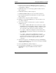
1 Setting Up the HP NetServer LXr 8000 Before You Set Up Your HP NetServer Before you set up your HP NetServer LXr 8000: • Read the Rack Installation Road Map. The Road Map shows how to set up the entire rack system. It will alert you to issues you must consider before installing the HP NetServer itself. The Road Map comes with the rack. • Read this chapter. This chapter tells how to set up and configure the HP NetServer. It tells you what to do, and in what order.
Chapter 1 Setting Up the HP NetServer LXr 8000 4. If you have options to add to the HP NetServer (memory, accessory boards, processor boards), remove the appropriate access panels from the computer. Refer to Chapter 3. 5. Install additional processors and voltage regulator modules, if desired. Refer to Chapter 7. 6. Install additional memory. Refer to Chapter 5. 7. Install PCI and PCI Hot Plug accessory boards. Refer to Chapter 6. 8. Reconnect all internal cables and reattach all covers and access panels.
Chapter 1 Setting Up the HP NetServer LXr 8000 15. Configure the HP NetServer with Configuration Assistant from the Navigator CD-ROM. Choose the Express Configuration option. Refer to Chapter 10. NOTE To fully configure the HP NetServer, all the rack components should be cabled and online (though not necessarily installed in the rack.) 16. If you plan to ship the fully-configured rack system to a different destination, label each cable and component.
2 Controls, Indicators, and Ports This chapter describes controls, indicators, and ports on the front and rear of the HP NetServer LXr 8000.
Chapter 2 Controls, Indicators, and Ports Power, Reset, and Secure Mode Buttons and LEDs The Power, Reset, and Secure Mode buttons are on the left side of the control panel. Power Button Reset Button Power LED Secure Mode LED Secure Mode Button Figure 2-2. Power, Reset, and Secure Mode Buttons and LEDs NOTE The HP NetServer’s front bezel includes a small plastic door that you can pull down over the Power Button and Reset button.
Chapter 2 Controls, Indicators, and Ports Table 2-1. Power, Reset, and Control Buttons and LEDs Control Description Turns server power on and off. Power Button Power LED Glows steady green when power is on, and flashing green when the system is in ACPI Sleep. If the LED is dark, system power is off. Performs a system hard reset. Reset Button Secure Mode Button Secure Mode LED Puts the system in Secure Mode, if your system was configured for Secure Mode.
Chapter 2 Controls, Indicators, and Ports Control Panel LCD Screen and Navigation Buttons The control panel features a two-line LCD screen that displays POST messages, boot messages, and errors. You can also use this screen to display system configuration information, a log of current and past error conditions, replaceable parts information, and more. Figure 2-3 shows the LCD and its navigation buttons.
Chapter 2 Controls, Indicators, and Ports Red Yellow Green Figure 2-4. Server Status LEDs Table 2-2. Interpreting the Server Status LEDs Red LED Yellow LED Green LED Off Off Off Main power is off. Server may or may not have standby power. Flashing Off Off A component of the server has failed. If the component was redundant (a power supply or fan, for example), the server may still be operating.
Chapter 2 Controls, Indicators, and Ports Rear Panel Indicators and Ports The HP NetServer’s rear panel includes communication ports, the AC inlet, and the server’s three power supplies. In addition, PCI Hot Plug slots on the I/O baseboard have their own LEDs, which are visible from the rear of the server. Figure 2-5 shows the rear of the HP NetServer. HP TopTools Remote Control Card and Connectors External SCSI Port Parallel, Serial, Keyboard, Mouse, Monitor Ports AC Inlet Power Supplies Figure 2-5.
Chapter 2 Controls, Indicators, and Ports Power Supply Module Indicators Each of the HP NetServer power supply modules has the indicators in Figure 2-6: PWR PRFL FAIL Figure 2-6. Power Supply LEDs Table 2-3. Power Supply Module LED Descriptions Control PWR (Power) Description Lights solid green when system is powered up. If the system is not powered up but is connected to AC power (so that standby voltage is available), the LED blinks green. If there is no AC power, the LED is dark.
Chapter 2 12 Controls, Indicators, and Ports NOTE Once lit, the PRFL (Predictive Fail) LED will continue to blink yellow even if the fan speed problem is intermittent and fan speed has again reached acceptable levels. To determine whether fan speed is currently a problem, you must cycle power to the power supply. The easiest way to do this is to pull out the power supply, wait at least 15 seconds, and then reinsert it.
Chapter 2 Controls, Indicators, and Ports Communication Ports Figure 2-7 identifies the ports on the HP NetServer’s rear panel. Keyboard Mouse External SCSI Port Com1 Com2 LPT1 VGA Not Used Figure 2-7. Rear Panel Ports PCI Hot Plug Slot LEDs Slots P7 through P10 on the I/O baseboard are 64-bit PCI slots that can be individually powered down through system software. This feature allows replacement of individual boards without powering down the entire server.
Chapter 2 Controls, Indicators, and Ports Table 2-4. Reading PCI Hot Plug Slot LEDs to Determine Slot Status Green LED Amber LED On Off Power to the slot is on, and the slot is operating normally. Do not remove the board from the slot. On On Power to the slot is on, but the slot needs attention. Do not remove the board from the slot. Off On Power to the slot is off, and the slot needs attention. You can remove the board from this slot. Off Off Power to the slot is off.
Chapter 2 Controls, Indicators, and Ports Connecting AC Power to Multiple-Server Configurations When you connect the HP NetServer to an AC power source, the server temporarily draws a large "inrush current." This occurs even when the system is in standby mode. Inrush current is much greater than the server’s normal operating current. Generally, the AC power source can handle the inrush current. If you install several HP NetServers on one circuit, however, precautions are necessary.
Chapter 2 Controls, Indicators, and Ports Table 2-5. Control Panel Display Control Buttons Button Name Description Return to previous menu. Escape Select an item from a menu. Enter Scroll down one line through the current screen or menu. Down Arrow Scroll up one line through the current screen or menu.
Chapter 2 Controls, Indicators, and Ports Only two lines of the main menu can appear on the display at one time. Use the control panel’s up-arrow and down-arrow buttons to scroll up and down through the menu selections. A cursor shows which line is currently selected. Lines that begin with a greater-than symbol (>) and have a blinking cursor are menu selections that lead to other menus. To choose a selection, use the arrow buttons to move the cursor to the appropriate line and then press the Enter button.
Chapter 2 Controls, Indicators, and Ports Mem slot1 xxxxMB Mem slot2 xxxxMB Press the front panel’s Escape button to return to the Main Menu. The FW Info (Firmware Information) Menu The FW Info menu displays the firmware versions of all firmware components in the sytem. You cannot enter information here, only view it. When you select FW Info from the Main Menu, you see something like this on the server’s front panel display: **FW Info*** BMC ver xx.
Chapter 2 Controls, Indicators, and Ports Press the front panel’s Escape button to return to the Main Menu. The Event Log Menu The Event Log menu allows you to get information about current and resolved events from the server’s event log. These may be errors, or normal system events like a system boot. The menu shows you a list of all events currently in the log. To see more information about one particular event, simply select it from the list.
Chapter 2 Controls, Indicators, and Ports Proc. 2 FRB3 Failure Use the front panel’s down-arrow key to scroll down through the entire entry. When finished, press the front panel’s Escape button to return to the Event Log menu. Press Escape again to return to the Main Menu. The HW P/N (Hardware Part Number) Menu The HW P/N displays the server chassis’ part number and serial number.
3 Opening and Closing the HP NetServer Removing and Replacing the Front Bezel The front bezel has three clips that mount onto a hinge. The hinge is secured to the front of the HP NetServer. You can swing the bezel open on its hinge, or remove the bezel entirely. To swing the bezel open, grasp it by the handle on its right edge and pull it open to the left. This exposes the mass storage bay and the memory board bays. To remove the bezel, pull it straight forward off the chassis.
Chapter 3 Opening and Closing the HP NetServer packed in the accessories tray in the HP NetServer’s shipping box. Opening and Closing the Server’s Top Cover You can remove all or part of the HP NetServer’s top cover: • You must power down the HP NetServer before taking off the top cover. Remove the entire cover for full access to the processor baseboard and I/O baseboard. • Remove the panel at the rear of the top cover for access to the four 64-bit PCI slots on the I/O baseboard.
Chapter 3 Opening and Closing the HP NetServer tools or jewelry. Disconnect any telephone cables to avoid exposure to shock hazard from telephone ringing voltages. 3. Remove the two Torx screws at the front of the cover, then slide the cover back approximately one half-inch. See Figure 3-2. 1. Remove screws 2. Pull back cover 1/2 inch Figure 3-2. Unfastening the Cover and Sliding It Back 4. Lift off the cover. See Figure 3-3.
Chapter 3 Opening and Closing the HP NetServer Figure 3-3. Lifting Off the Cover 5. To replace the cover, lower it onto the top of the server, about a half-inch to the rear of its normal position when closed. See Figure 3-2. 6. Push the cover forward until the slots in its front edge line up with the screw holes on the server’s chassis. 7. Reattach the screws.
Chapter 3 Opening and Closing the HP NetServer To remove the PCI Hot Plug access panel and reach the hot-plug slots: 1. Remove the Torx screws that fasten the access panel to the rest of the top cover. Push the panel back about one half-inch. 1. Remove screws 2. Push panel back 1/2 inch Figure 3-3.
Chapter 3 Opening and Closing the HP NetServer 2. Lift the access panel away from the top cover. See Figure 3-4. Shield blocks access slots that do not support PCI Hot Plug Figure 3-4. Lifting Off the Access Panel NOTE After you remove the access panel, a metal shield blocks your access to I/O slots P1 through P6, the slots that do not support PCI Hot Plug operation. To reach these slots, power down the server and remove the entire top cover. The shield then lifts off easily. 3.
4 Installing Mass Storage Devices Introduction The HP NetServer supports Fast/Wide SCSI for internal devices. Ultra-SCSI devices, if installed, run as Fast/Wide devices. The internal CD-ROM drive is an IDE device. The HP NetServer accepts these mass storage devices: • Hewlett Packard hot-swap SCSI hard disk drives • CD-ROM and tape drives • Flexible disk drive NOTE Some devices, including some DAT drives, may need an adapter to connect to the server’s internal SCSI cable.
Chapter 4 Installing Mass Storage Devices 6. Slots P2 through P10 On-board SCSI consists of two channels, A and B. Channel A controls the HP NetServer’s internal hard disk drives. Channel B handles the HP NetServer’s external SCSI port. On each SCSI channel, the server scans for a boot device starting at device ID 0 and works up from there. Installing a Hot-Swap Hard Disk Drive CAUTION Protect the drive from static electricity by leaving it in its anti-static bag until you are ready to install it.
Chapter 4 Installing Mass Storage Devices Hot Swap Drive Filler Plug Figure 4-1. Hot Swap Drive and Filler Panel 2. On the drive, press the locking latch in and pull the ejector handle out as far as it can go, as shown in Figure 4-2. CAUTION Be careful when you open the ejector handle. Extreme force can snap off the handle.
Chapter 4 Installing Mass Storage Devices Locking tab pivots when the ejector handle is open Light Pipes (fragile) Ejector Handle Locking Latch Figure 4-2. Readying Drive For Installation 3. Slide the drive slowly and gently into the location until it stops. (See Figure 4-1.) CAUTION Be careful not to damage the light pipes as you insert the drive. They are very fragile. 4. Press the ejector handle in until you feel the latch click into place.
Chapter 4 Installing Mass Storage Devices Removing a Hot-Swap Hard Disk Drive CAUTION You must remove the drive slowly to ensure that the drive heads are parked prior to removal. Be sure to follow these instructions carefully to prevent handling damage, such as head slaps or head actuator unlocking . 1. To unlock the drive, push the locking latch in and then pull the ejector handle toward you. See Figure 4-3. Pull locking latch completely open before pulling out the drive Figure 4-3.
Chapter 4 Installing Mass Storage Devices 4. Use your hand to support the bottom of the drive. Slowly pull the drive straight out. Do not allow the drive to fall . 5. Place the drive in an electrostatic protected container. Do not stack drives.
5 Installing Additional Memory Introduction This chapter includes guidelines and instructions for: • Removing and reinstalling a HP NetServer LXr Pro 8000 memory board for a memory upgrade • Installing DIMMs in the specified configuration s on the memory board • Removing DIMMs and downsizing the memory configuration Figure 5-1.
Chapter 5 Installing Additional Memory Memory Configuration Guidelines The HP NetServer is equipped with two memory boards. You remove and insert the board through the front of the server. The boards sit horizontally in two side-by-side bays, and plug into connectors on the server’s midplane board. Each memory board supports four-way interleaving between its own DIMMs. There can also be board-to-board interleaving if both boards are populated identically.
Chapter 5 NOTE Installing Additional Memory Keep both memory boards in the HP NetServer during operation, even if the secondary board has no DIMMs. The empty board acts as a terminator for the memory board slot. A memory board has 16 DIMM sockets and accepts 64 MB or 256 MB buffered EDO DIMMs (50 ns). Each board has a maximum capacity of 4096 MB when fully populated with 256 MB DIMMs. The minimum memory configuration is four 64 MB DIMMs on the main memory board (in slots J1, J2, J3, and J4).
Chapter 5 Installing Additional Memory Key: Bank A (Slots J1, J2, J3, J4) Bank B (Slots J5, J6, J7, J8) Bank C (Slots J9, J10, J11, J12) Bank D (Slots J13, J14, J15, J16) J1 J2 J5 J6 J9 J10 J13 J14 J3 J4 J7 J8 J11 J12 J15 J16 Figure 5-3. DIMM Slot Numbers and Bank Numbers Please note the following DIMM installation guidelines before adding memory: • Add (or remove) DIMMs to the memory board in groups of four. Each group of four DIMMs must fill one bank on a memory board.
Chapter 5 Installing Additional Memory • All DIMMs within a bank must be identical in size and speed. A bank must contain either all 64 MB DIMMs or all 256 MB DIMMs. • Banks of 64 MB DIMMs and 256 MB DIMMs can coexist on the same memory board. • The minimum memory configuration is four 64 MB DIMMs in one bank on the primary (right-hand) memory board, and no DIMMs on the left-hand board. When the system has two memory boards but only four DIMMs, all four DIMMs must be on the primary memory board.
Chapter 5 Installing Additional Memory Key: Bank A Bank B Bank C Bank D Primary Board Secondary Board J1 J1 J2 J2 J5 J5 J6 J6 J9 J9 J10 J10 J13 J13 J14 J14 J3 J3 J4 J4 J7 J7 J8 J8 J11 J11 J12 J12 J15 J15 J16 J16 Board-to-Board Interleaving: 8 DIMMS Primary Board Secondary Board J1 J1 J2 J2 J5 J5 J6 J6 J9 J9 J10 J10 J13 J13 J14 J14 J3 J3 J4 J4 J7 J7 J8 J11 J12 J15 J16 J8 J11 J12 J15 J16 Board-to-Board Interleaving: 16 DIMMS Figure 5-4.
Chapter 5 Installing Additional Memory Key: Bank A Bank B Bank C Bank D Primary Board Secondary Board J1 J2 J5 J6 J9 J10 J13 J14 J1 J2 J5 J6 J9 J10 J13 J14 J3 J4 J7 J8 J11 J12 J15 J16 J3 J4 J7 J8 J11 J12 J15 J16 Board-to-Board Interleaving: 24 DIMMS Primary Board Secondary Board J1 J2 J5 J6 J9 J10 J13 J14 J1 J2 J5 J6 J9 J10 J13 J14 J3 J4 J7 J8 J11 J12 J15 J16 J3 J4 J7 J8 J11 J12 J15 J16 Board-to-Board Interleaving: 32 DIMMS 39
Chapter 5 Installing Additional Memory Figure 5-5. 24-DIMM and 32-DIMM Configuration for Interleaved Memory Boards Removing and Replacing the Memory Board To remove the memory board, follow this procedure: 1. Log off all users. Back-up files. Follow instructions in your network operating system (NOS) documentation to gracefully shut down all networking software and applications. 2. Press the power switch on the HP NetServer’s control panel when prompted by the operating system.
Chapter 5 Installing Additional Memory 1. Pull up on LCD handle. LCD slides up about 1/2 inch Memory Access Panel 2. Loosen captive screws on memory access panel. Remove panel. Captive Screws Figure 5-6. Gaining Access to the Memory Board Bays 6. The memory bays are protected by an access panel. Loosen the three captive screws that hold the panel in place, and then remove the panel. See Figure 5-6.
Chapter 5 Installing Additional Memory 7. The memory boards sit side by side underneath the processor baseboard. Choose the board you want to remove, and pull open the two retaining latches that hold it in place. See Figure 5-7. Retaining Latches 1. Pull open retaining latches on memory board. 2. Pull board from its slot Figure 5-7. Removing and Replacing a Memory Board 8. Hold the memory board by the corners, and carefully pull the board from its slot. See Figure 5-7.
Chapter 5 Installing Additional Memory 11. To replace the memory board, hold it in front of its bay, with the component-side down. The end of the board with the connector must point into the memory board bay. 12. Slide the board into the guide rails on either side of the memory board bay. Push the board in until it seats in the slot at the rear of the bay. See Figure 5-8. Guide Rails Memory Board Figure 5-8. Replacing the Memory Board 13. Close the memory board’s retaining latches.
Chapter 5 Installing Additional Memory Installing DIMMs on a Memory Board Follow these steps to install a DIMM in a slot on a memory board. CAUTION Use only DIMMs acquired from HP. Contact HP Customer Support for a list of qualified DIMMs. HP will not support configurations that use non-HP Buffered EDO DIMMs. 1. Remove the memory board from the computer. See the previous section, "Removing and Replacing the Memory Board." 2. Place the board on a firm, anti-static surface.
Chapter 5 Installing Additional Memory Figure 5-11. Installing a DIMM Module 5. Align the notches on the DIMM with the notches on the socket. 6. Hold the DIMM so that the front edge faces straight down into the connector (at a 90 ° angle to the memory board). 7. Insert the DIMM carefully into the desired slot. The retaining clips will grasp the DIMM automatically if it is inserted properly. CAUTION Do not rock the EDO DIMM into place, but apply firm and even pressure.
Chapter 5 Installing Additional Memory Removing DIMMs You may need to remove a bank of DIMM modules to downsize your memory configuration, or to replace a defective DIMM. Follow these guidelines for removing DIMMs. • If reducing the number of DIMMs on the board, remove them only in increments of one full bank (four DIMMs). • When you finish removing DIMMs, the remaining DIMMs should be arranged on the board in one of the configurations shown in Figures 5-4 and 5-5.
Chapter 5 Installing Additional Memory 7. Open the retaining clips of the first DIMM just enough so that you can lift the DIMM’s top edge away from the clips. 8. Lift the DIMM completely away from the socket. 9. Place the DIMM in its anti-static container. 10. Repeat steps 5-9 for the other three DIMMs in the bank. CAUTION Close all retaining clips on the memory board before inserting it into your NetServer. This includes clips on empty slots as well as those on slots containing DIMMs.
6 Installing Additional Boards Introduction This chapter tells how to install accessory I/O boards in the HP NetServer LXr 8000. The server supports up to ten full-length PCI boards, four of which support PCI Hot Plug operations. The I/O Baseboard All accessory boards plug into the I/O baseboard at the rear of the server’s chassis. The baseboard has the following slots: • Four 64-bit full-length PCI slots. These four slots can support Hot Plug operations for PCI cards with the appropriate driver software.
Chapter 6 Installing Additional Boards Battery SCSI A IDE Floppy Disk SCSI B I2CConnector J1D1(for Remote Control Card Jumper Block 10 9 8 7 PCI Hot-Swap Slot Connectors 6 5 4 3 2 PCI (Not Hot-Swap) Slot Connectors 1 System I/O Connector Shared PCI/ISA Slot Connectors TopTools Remote Control Card must be in Slot 2 Figure 6-1. I/O Baseboard NOTE 50 You will find information about setup and use of the HP TopTools Remote Control card in HP Information Assistant.
Chapter 6 Installing Additional Boards PCI Hot Plug Support The four slots that support PCI Hot Plug operations, P7 through P10, are called the PCI Hot Plug slots. They support 32-bit and 64-bit cards, with or without PCI Hot Plug drivers. NOS Support for PCI Hot Plug The PCI Hot Plug feature is only operational in a Hot Plug slot if the network operating system (NOS) supports PCI Hot Plug, and if the board in the slot has PCI Hot Plug device drivers.
Chapter 6 Installing Additional Boards CAUTION The Hot Plug board bracket must be in place for all boards, even those that do not support PCI Hot Plug. Removing the bracket cuts power to the slot. • A PCI Hot Plug access panel in the top of the HP NetServer which provides access to the PCI Hot Plug slots even when the server is operating. • Indicator LEDs next to each PCI Hot Plug slot on the I/O baseboard.
Chapter 6 Installing Additional Boards Tools Required These tools are required for removal and installation of accessories: • T-15 Torx driver • An anti-static service kit (3M 8501/8502/8503 or equivalent). This kit includes a static-dissipating work surface, a chassis clip lead, and a wrist strap. Installing Boards NOTE Some full-length PCI boards have a plastic "handle" (board extender) on one end.
Chapter 6 Installing Additional Boards 3. Press the power switch on the HP NetServer’s control panel when prompted by the operating system. Normally, this is the complete procedure. NOTE The power supplies will continue to provide standby current to the NetServer until the power cable is disconnected. 4. Disconnect the power cord and signal cables, and if necessary, label them to support reassembly. 5. Pull the server out from the rack on its slides. Then remove the top cover.
Chapter 6 Installing Additional Boards 7. Consider the HP NetServer’s boot order when selecting a slot on the I/O baseboard (Figure 6-1). If you are installing a SCSI controller board, the priority of the controllers (where the BIOS will search for the boot drive) is set by the board’s slot location. Refer to "I/O Board Boot Order" earlier in this chapter. 8. When you have selected a slot, remove its slot cover on the server's rear panel.
Chapter 6 Installing Additional Boards 9. Push the board down into its connector on the I/O baseboard. See Figure 6-4. Figure 6-4. Inserting the Board 10. Screw the board’s I/O bracket to the HP NetServer’s I/O panel. If the board is in one of the PCI Hot Plug slots (P7 through P10): a. Put the board’s I/O bracket in place on the I/O panel. Line the screw hole on the bracket up with the matching hole on the I/O panel, but do not screw it in. b. Replace the Hot Plug board bracket.
Chapter 6 Installing Additional Boards PCI Board Bracket Hot-Plug Board Bracket I/O Panel Captive Screw Figure 6-5. Replacing the Hot-Plug Board Bracket CAUTION The lower end of the Hot Plug board bracket should press firmly against a switch on the I/O baseboard. This switch controls power to the slot in question. If the bracket does not press firmly on the switch, power may not be available in this slot when the server boots. 11.
Chapter 6 Installing Additional Boards Hot Replacement of Hot-Plug Boards NOTE Some full-length PCI cards have a plastic "handle" (board extender) on one end. If the board you are installing has one, you may need to remove the handle to make the board fit in the HP NetServer. To replace one PCI Hot Plug board with another while the server is running, you must: • Turn off power to the slot through your server’s NOS. • Physically remove the hot plug board and replace it with another.
Chapter 6 Installing Additional Boards Figure 6-6. PCI Hot Plug Interface CAUTION Never remove a PCI Hot Plug board from a hot-plug slot without first powering down the slot through software. Doing so interferes with the operation of the board’s Hot Plug driver. As a consequence, the board will not resume I/O operation when replaced. Also, you will not be able to power up the slot again through software.
Chapter 6 Installing Additional Boards 4. The interface shows the current status of each PCI Hot Plug slot. Next to the name of each slot are graphic representations of two LEDs, one green and one amber. These show the same reading as the slot’s LEDs on the I/O baseboard. Table 6-1 shows the meaning of these LEDs. Table 6-1. Reading Hot Plug PCI Slot LEDs to Determine Slot Status Green LED Amber LED On Off Power to the slot is on, and the slot is operating normally.
Chapter 6 Installing Additional Boards 10. Put the board’s I/O bracket in place on the rear panel of the server (See Figure 6-5). Line the screw hole on the bracket up with the matching hole on the server, but do not screw it in. 11. Replace the Hot Plug board bracket. It fits over bracket. The captive screw in the Hot Plug board bracket must line up with the screw hole in the board’s I/O bracket and the matching hole on the server (Figure 6-5).
7 Installing Additional Processors Introduction This chapter tells how to install processors in the HP NetServer LXr 8000. The HP NetServer has four processor slots on its processor baseboard, and comes standard with one processor installed and terminators in the other three slots. The server supports 400 Mhz Pentium II Xeon processors with 512K or 1 MB caches. (The server will support 450 Mhz Pentium II Xeon processors with 512k, 1 MB, or 2MB caches, when the processors become available.
Chapter 7 Installing Additional Processors Unpack the shipping box and check the contents against its packing list. The upgrade kit should include: • Processor NOTE Be sure to keep the bag around the processor sealed until you are ready to install the board. • Voltage regulator modules • HP NetServer Processor Upgrade Guide NOTE 64 When the HP NetServer LXr 8000 is configured with multiple processors, all the processors must have the same frequency, stepping, and cache size.
Chapter 7 Installing Additional Processors The Processor Baseboard The HP NetServer’s processor baseboard has four processor slots, numbered 1 through 4. It also has six voltage regulator module slots, numberedVRM1 through VRM6. Figure 7-1 shows where to find these slots on the processor baseboard. VRM 2 VRM 6 VRM 1 VRM 4 VRM 5 Jumper Block J31 VRM 3 Processor 1 Front of NetServer Processor 2 Processor 3 Processor 4 Figure 7-1. Processor Baseboard The first CPU is always in the Processor 1 slot.
Chapter 7 Installing Additional Processors If you are upgrading from 400 MHz to 450 MHz processors (or downgrading from 450 MHz to 400 MHz), you must change the jumper settings in jumper block J31 on the processor baseboard. See Figure 7-2 for the appropriate jumper settings. Installing the Processor CAUTION The processors are sensitive to static electricity, and can be easily damaged by improper handling.
Chapter 7 Installing Additional Processors Table 7-1.
Chapter 7 Installing Additional Processors CAUTION Wear a wrist strap and use a static-dissipating work surface connected to the chassis when handling components. Ensure that the metal of the wrist strap contacts your skin. 5. Put on the antistatic wrist strap and place the antistatic mat on a firm surface near the system. Connect the strap and mat to an unpainted metal surface on the system chassis. 6. Remove the server’s top cover. See Chapter 3 for details. 7.
Chapter 7 CAUTION Installing Additional Processors All processors on the baseboard must have the same speed, cache size, and stepping. You cannot, for example, mix 400 MHz processors that have different-sized caches, nor can you mix 400 MHz and 450 MHz processors. 8. Loosen the captive screws that hold the down the lid of the processor cage. Swing open the lid until it points straight up, then lift it out. See Figure 7-3. Figure 7-3.
Chapter 7 Installing Additional Processors 9. On the CPU baseboard, remove the terminator from the slot you will put the processor in. (See Table 7-1.) Pull up the two retaining latches on top of the terminator. Then lift the terminator out of its slot. See Figure 7-4. 1. Pull up retaining latches 2. Lift processor out of slot Figure 7-4.
Chapter 7 Installing Additional Processors 10. Remove the processor from its sealed bag. Make sure that the retaining latches on top of the processor are open (pointing straight up). Then firmly push the processor into its slot in the processor cage. Make sure that it seats firmly in its connector. See Figure 7-5. Figure 7-5. Installing a Processor NOTE You are not required to use the HP NetServer Navigator CDROM to reconfigure your system after installing the new processor board.
Chapter 7 Installing Additional Processors 11. Push the retaining latches closed. In the closed position, the latches should grab the rails on either side of the processor cage. See Figure 7-6. Figure 7-6.
Chapter 7 Installing Additional Processors 12. On the CPU baseboard, install additional VRMs in the VRM slots. (Table 7-1 tells you how many VRMs to install, and what slots to install them in.) Push each VRM firmly into its slot until you hear a click. See Figure 7-7. NOTE VRM slots 5 and 6 are in a narrow space between the processor cage and the side of the chassis. For easier access to these slots, you can temporarily remove the adjacent wall of the processor cage.
Chapter 7 Installing Additional Processors 13. Replace the lid of the processor cage. Insert the tabs on one end of the lid into the matching slots on the rim of the cage. Then lower the lid into place and fasten the captive screws. See Figure 7-8. 2. Lower lid and fasten captive screws 1. Insert tabs on lid into slots on rim of cage Figure 7-8. Closing the Processor Cage Lid 14. Replace the cover of the chassis. See Chapter 3. 15. Reconnect the power cord and signal cables.
8 Mounting the Server in the Rack Introduction This chapter tells how to mount the HP NetServer in a HP System/E or System/U rack. The illustration below shows the characteristics of the System/E and System/U racks. If you have the older HP Systems rack, see Chapter 13 for instructions. (If you are mounting the server in a non-HP rack, refer to the separate rack-mounting guide for third-party racks. It is packed in the accessories tray in the HP NetServer’s shipping box.
Chapter 8 NOTE Mounting the Server in the Rack If you want to put your NetServer into a third-party rack, you may be able to find relevant documentation on HP’s web site at the following URL: http://www.hp.com/netserver/servsup The HP NetServer rack mount kit requires seven EIA units of space in the rack. Before mounting the server, plan the server’s location in the rack relative to other rack components. Proper placement is vital both for safety and operating efficiency.
Chapter 8 Mounting the Server in the Rack Installation Basics Safety Precautions Always keep the following safety and environmental issues in mind, especially if you install the HP NetServer in a non-HP rack environment: • Maximum Recommended Ambient Temperature. The maximum recommended ambient temperature of the room is 35 °C. • Elevated Operating Ambient Temperature. The ambient operating temperature within a closed or multi-unit rack assembly may exceed the room’s ambient temperature.
Chapter 8 Mounting the Server in the Rack HP NetServer Rack Mount Parts List Makes sure that the rack-mount kit that accompanies the HP NetServer contains the following parts: Table 8-1.
Chapter 8 Mounting the Server in the Rack 3. Slide the rack nuts onto the column where indicated on the template. (See Figure 8-2.) If you don’t have the template, Figure 8-3 shows rack nut placement for the front columns. Figure 8-2.
Chapter 8 Mounting the Server in the Rack # Rear of Rack # Right Left "#" represents the EIA unit numbers on the rack columns # Sixth Hole From Bottom # Bottom of Server # Attach nuts to this face of the rear columns Fourth Hole From Bottom Figure 8-4. Rack Nut Locations on the Rack’s Rear Columns Step 2: Attaching the Slides to the Rack 1. Pull the stabilizing foot forward out of the bottom of the rack. Figure 8-5 shows the stablizing foot. 2.
Chapter 8 Mounting the Server in the Rack Extend rack’s stablizing foot from front of rack for safety Figure 8-5. Securing the Slide to the Rack Columns 3. With the slide pushed firmly into position, insert two screws through the slide’s front bracket into the left-front column. Fasten the screws only loosely at first, so that the bracket can settle into the lowest possible position. Then tighten the screws until they hold the bracket firmly to the column. 4.
Chapter 8 Mounting the Server in the Rack Step 3: Placing the HP NetServer in the Rack WARNING If you have not done so already, pull the rack’s stabilizing foot forward out of the bottom of the rack to prevent rack instability while mounting the HP NetServer. Failure to do so could result in injury and equipment damage. Figure 8-5 shows the stabilizing foot in position. 1. Before lifting the HP NetServer, remove all three power supply modules.
Chapter 8 WARNING Mounting the Server in the Rack With power supplies in place, the HP NetServer does not balance evenly when lifted by its handles. Two people may have difficulty holding the HP NetServer level enough to fasten it to the slides. Removing the power supplies improves the balance of the HP NetServer and reduces the likelihood of accidents. 2. Pull out both slides until their slide members are fully extended (Figure 8-7). When you do this, the slides lock into position.
Chapter 8 Mounting the Server in the Rack 3. With the help of at least one other person, lift the server by its four handles. Move the server between the extended slide members, so that the slides are underneath the server’s handles on each side. See Figure 8-8. 1. Move server onto slides. 2. Fasten slides to server with screws (four screws per slide) Handles Figure 8-8. Mounting the Server on the Slides 4. Lower the server onto the slide members.
Chapter 8 Mounting the Server in the Rack 6. Remove the screws that attach the handles to the server . (See Figure 8-9). Take the handles off the server. Store the handles and screws in a convenient place. Reattach the handles whenever you remove the server from the rack. (If you plan on shipping the server elsewhere, always pack it with the handles attached.) Figure 8-9. Removing the Mounting Handles 7. Press in the release latches on each slide, and push the server all the way back into the rack.
Chapter 8 Mounting the Server in the Rack Press in the release latch on each slide and push the server into the rack Flanges Figure 8-10. Pressing in the Release Latches 8. Each of the server’s two front flanges has two slots. These slots should line up with rack nuts that you previously mounted on the rack columns. Insert screws through the flanges into the rack nuts, and fasten the server in place so it cannot slide.
Chapter 8 Mounting the Server in the Rack 2. Insert hooks into matching holes on front of server 3. Swing hinge open (to the left) 1. Push hinge against front of server Figure 8-11. Pressing the Bezel Hinge onto the Front of the HP NetServer 2. Swing the hinge open, to the left. See Figure 8-11. 3. Looking through the open side of the hinge, you see three raised holes for screws. These align with holes on the server itself. Insert screws into these three holes and hand-tighten them. See Figure 8-12.
Chapter 8 Mounting the Server in the Rack 1. Insert screws into holes through open side of hinge 2. Swing hinge closed (to the right) 3. To tighten screws, insert driver through access holes in top of hinge. Hinge in open position Hinge in closed position Figure 8-12. Fastening the Bezel Hinge to the Chassis 4. Swing the hinge closed. Use the access holes in the top of the hinge to insert a driver and finish tightening the three screws.
Chapter 8 Mounting the Server in the Rack 5. Attach the bezel latch to the server with screws. See Figure 8-13. Figure 8-13. Attaching the Bezel Latch 6. Hold the bezel in front of the server. Line it up with the hinge and bezel latch, and then press it firmly into place, especially at the top-left and bottom-left corners. You should hear several clicks as the bezel fits into place on the hinge and latch. See Figure 8-14.
Chapter 8 Mounting the Server in the Rack Figure 8-14. Attaching the Bezel to the HP NetServer Step 5: Continuing with the Rack Installation Process After you install the HP NetServer in the rack, refer to the Rack Installation Road Map to continue with the process of installing and configuring your HP rack system.
9 Connecting the Monitor, Keyboard, Mouse, and UPS Introduction This chapter explains how to connect a monitor, keyboard, mouse and Uninterruptible Power Supply (UPS) to the rear of the HP NetServer. Connecting the Monitor, Keyboard, Mouse, and UPS Follow this procedure: 1. Connect the monitor, keyboard and mouse to the HP NetServer LXr 8000. Figure 9-1 shows which port to use for each device. Keyboard Mouse Com1 Com2 LPT1 VGA Not Used Figure 9-1.
Chapter 9 Connecting the Monitor, Keyboard, Mouse, and UPS NOTE If you have a console switch box, refer to the switch box’s user guide for instructions on connecting the keyboard, mouse, and monitor. NOTE The Keyboard and Mouse ports are interchangeable. You can plug the keyboard into the Mouse port, if you want, or the mouse into the Keyboard port. 2. If you have a UPS (Uninterruptible Power Supply) installed in the rack , turn it on.
10 Configuring the System HP NetServer Navigator CD-ROM The HP NetServer Navigator CD-ROM Main Menu directs you to modules where you can perform configuration tasks or access online system documentation. You may choose to configure your system either before or after you install it in the rack. For more information, see Chapter 1 of this manual and see also the HP Rack Installation Road Map.
Chapter 10 Configuring the System XXXX Document Number Figure 10-1. Location of Document Number on Navigator CD You can obtain the Release History and Status Report for your CD-ROM in one of these ways: • Fax--Call HP’s fax system at 1-800-333-1917 (or 1-208-344-4809 from your fax machine) and request document number 6005 • Internet WWW-http://www.hp.com:80/netserver/support/news_main.html • Internet FTP--ftp://ftp.hp.com/pub/servers • CompuServe--GO HPPC; download 6005.
Chapter 10 Configuring the System When you start Configuration Assistant, it first asks if you want to run the Hardware Verification and Labeling Utility. This utility checks whether your rack system is ready for configuration: it can check cabling connections, check the health of hardware components, create an asset inventory list of your components, and label mass storage devices. HP recommends that you run this utility before continuing with Configuration Assistant.
Chapter 10 Configuring the System • DiagTools: This step provides an easy-to-use hardware diagnostic for system verification, burn-in, and rapid troubleshooting. In Custom configuration, you can perform the configuration steps in any order. Select Custom if you are experienced in HP NetServer configuration and wish to configure the server in a particular order or one component at a time.
Chapter 10 Configuring the System • View of critical server information, such as the BIOS version, and PCI slot contents, SMP information, serial and parallel ports, and security status, from a single network management console • Control of management console from a remote PC, allowing the same features to be used at a local management console or non-networkconnected remote PC HP TopTools for Servers is new browser-based management software that provides remote administration and monitoring of critical s
Chapter 10 Configuring the System HP NetServer Utilities HP NetServer Utilities takes you to a menu where you can directly execute utilities such as the following: • DiagTools: An easy-to-use hardware diagnostic for system verification, burn-in, and rapid troubleshooting • Event Log Report Utility: Displays all logged server management events, Power-On Self Test (POST) errors and other system events • Diskette Library: Allows you to conveniently generate any flexible disk available on the HP NetServer
Chapter 10 Configuring the System The following sections tell how to access the setup utility, and how to perform selected tasks. Starting the Setup Utility To reach the setup utility, boot or reboot the system. After the first boot messages are displayed, this prompt appears: Press to enter SETUP Press F2 while the prompt is displayed. More boot messages appear, followed by the message Entering Setup...
Chapter 10 Configuring the System Using the Setup Screens Online help explains the settings displayed on the Setup. You also get instructions for navigating between the screens and entering or changing the setup data. • Press the right-arrow and left-arrow keys to move between selections on the menu bar. The menu bar is present at the top of most screens . • Press the up-arrow and down-arrow keys to move between fields on each screen. The currently-selected field is highlighted.
Chapter 10 Configuring the System 3. Use the arrow keys to move to the Set User Password or Set Supervisor Password field. Then press the Enter key. 4. A dialog box appears. In the Enter New Password field, type in the new password and press Enter. (For security, the password does not appear on the screen.) NOTE To leave the dialog without entering a password, press the Esc key at any time. 5. In the Confirm New Password field, type the password again. Then press the Enter key. 6.
Chapter 10 Configuring the System Changing the Boot Priority of Internal Devices You can change the boot priority of the server’s internal mass storage devices: the CD-ROM, the floppy drive (or other removable device), and hard drives connected to the server’s internal SCSI ports. To do this: 1. Use the right-arrow or left-arrow key to select Boot from the Setup menu. As soon as you do this, the Boot screen appears. 2. Use the down-arrow key to move to the Boot Device Priority field.
Chapter 10 Configuring the System 5. Press F10 to save the configuration changes and exit. The server reboots. Re-enabling a Disabled Processor If a processor is disabled during the HP NetServer’s power-on self-test (POST), you can re-enable it through the setup utility: 1. Start the setup utility. 2. Use the right-arr ow of left-arrow key to go to the Server menu. Once there, use the down-arrow key to go to the Server Processor Retest field. Choose Yes. 3.
11 Information Assistant Overview The HP NetServer Online Documentation CD-ROM includes Information Assistant, which contains the entire set of documentation for your NetServer. Information Assistant provides a quick and efficient means to locate information about installing, managing and servicing your NetServer.
Chapter 11 Information Assistant Search for a word or phrase using Search. Search performs fulltext searches for topic text. It not only takes you to the topic found, but highlights the word or words found by the search. You can use search operators such as AND, OR, NOT, and NEAR to further narrow your search. Select a Product button. Each button represents a product or group of products. Go to a topic with Previous button. Displays the previous topic in a module. Go to a topic with Next button.
Chapter 11 Information Assistant To print topics in Information Assistant, use one of the print options on the File drop-down menu. You can choose to print the current topic or all of the topics in a product book. After selecting the print option, the Windows Print dialog box appears. Print options vary with the capabilities of your printer. Installing HP Information Assistant Software HP Information Assistant runs on a PC running Windows 3.1 and above, Windows 95 or Windows NT.
12 Troubleshooting Precautions WARNING Before removing the top cover, always disconnect the power cord and unplug telephone cables. Disconnect telephone cables to avoid exposure to shock hazard from telephone ringing voltages. Disconnect the power cord to avoid exposure to high energy levels that may cause burns when parts are short-circuited by metal objects such as tools or jewelry. Note that the power switch does NOT turn off the standby power.
Chapter 12 Troubleshooting ◊ List of Error Messages and Beep Error Messages • The HP NetServer Navigator CD-ROM contains HP NetServer Utilities: At the HP NetServer Navigator Main Menu, select "Access NetServer Utilities" to use the following tools: ◊ HP DiagTools Utility: An easy-to-use hardware diagnostic for system verification, burn-in, and rapid troubleshooting. DiagTools is a floppydisk based tool. When you select DiagTool from the utilities menu, you are prompted to enter a floppy disk.
Chapter 12 Troubleshooting Common Installation Problems The following sections contain general procedures to help you locate installation problems. If you need assistance, it is recommended that you contact your reseller first. If you require assistance from Hewlett-Packard, see the "Warranty and Service/Support Booklet" included with your product. Troubleshooting Sequence To troubleshoot an installation problem, do the following: Check all cable and power connections, including those in the rack, etc.
Chapter 12 Troubleshooting If the System Will Not Power On Follow these steps: (add rack steps) 1. On the control panel, check to see if the LCD screen’s backlight is lit. If it is, the system is receiving AC power. If it is not lit, make sure that the server’s power cord in connected. 2. Check the HP NetServer’s power supplies. Each power supply has three LEDs.
Chapter 12 Troubleshooting If the System Passes the POST (Power-On Self Test) but Will Not Function If an error message displays on the screen, read the error message text for actions to take. If the actions do not solve your problem, contact your reseller. If there is no error message, follow these steps: 1. Turn off the server and remove all external peripherals, except the monitor and keyboard. Boot from an internal hard drive and see if the server now works. 2.
Chapter 12 Troubleshooting Error Messages If you get an error message, an error message utility on the Navigator CD-ROM can help you find a possible solution. When the HP NetServer displays an error message: 1. Insert your HP Navigator CD-ROM into the CD-ROM drive and press the Reset button on the front of the HP NetServer. 2. The HP NetServer boots from the CD-ROM. The error message utility automatically displays the error message and a problem-solving procedure.
13 Alternative Rack Mounting Introduction This chapter tells how to mount the HP NetServer in an HP Systems rack. Figure 13-1 shows the Systems rack. If you have the newer HP System/E or System/U racks, go to Chapter 8. If you are mounting the server in a non-HP rack, see the documentation in the appropriate rack accessory kit. a b c Characteristics of HP System Rack: d a. b. c. d. e.
Chapter 13 Alternative Rack Mounting The HP NetServer rack mount kit requires seven EIA units of space in the rack. Before mounting the server, plan the server’s location in the rack relative to other rack components. Proper placement is vital both for safety and operating efficiency. For more details, see the Rack Installation Road Map and the HP NetServer Rack Assembly and Cabling Reference Guide. NOTE Mounting the HP NetServer in its rack may or may not be the final step in the installation procedure.
Chapter 13 Alternative Rack Mounting room’s ambient temperature. Make sure that the temperature within the rack itself does not exceed 35°C. • Reduced Air Flow. As you mount equipment in the rack, make sure that you allow enough air flow for safe operation of the equipment. • Mechanical Loading. Uneven mechanical loading within the rack can cause hazardous conditions. Plan the placement of equipment in the rack to make sure that this problem does not occur.
Chapter 13 Alternative Rack Mounting 4 Rack Nut Screws (M5 x 16mm) 8 Screws for Slides (8-32 x ¼ inch) 1 Template Step 1: Attaching Rack Nuts to the Rack CAUTION If other rack components are to be mounted in the rack below the HP NetServer, install those components before starting to mount the server. NOTE Use the HP Rack Assistant software to determine where in the rack to mount the HP NetServer. In this step, you attach rack nuts to the front columns of the HP Systems rack.
Chapter 13 Alternative Rack Mounting 3. Slide the rack nuts onto the column where indicated by the template. If you don’t have the template, Figure 13-2 shows rack nut placement for the front columns. Right Left Seventeenth Hole From Bottom Front of Rack Ninth Hole From Bottom Attach nuts to this face of left-front and right-front rack columns Bottom of Server Figure 13-2. Rack Nut Placement on Front Rack Columns 4. Attach rack nuts to the other front rack column. Repeat steps 2 and 3.
Chapter 13 Alternative Rack Mounting Step 2: Attaching the Slides to the Rack Before fastening the slides in the rack, you must detach the slides’ mounting flanges. They are not used in the HP System Rack. Instead, studs on the slide insert in holes on the inside face (the side) of the rack columns. 1. Use a nut driver or wrench to detach the two mounting flanges from each slide. See Figure 13-3. Slide Brackets Figure 13-3. Removing the Slides’ Mounting Flanges 2.
Chapter 13 Alternative Rack Mounting Left Rear Studs on slides will mount through this face of columns Left Front Stud on slide will mount in fifth hole from bottom of server. Mark hole for reference. Right Rear Studs on slides will mount through this face of columns Right Front Bottom of Server Figure 13-4. Mounting Hole Placement for the Slides 4. Again, hold the template alongside the inside face of the left-rear rack column. Again, the template directs you to a single rack-column hole.
Chapter 13 Alternative Rack Mounting d. Tighten nuts on both the screws. Figure 13-5. Securing the Slides to the Rack 6. Attach the other slide to the right-front and right-rear rack colu mns. Repeat Steps 1-3.
Chapter 13 Alternative Rack Mounting Step 3: Placing the HP NetServer in the Rack WARNING If you have not done so already, pull the rack’s stabilizing foot forward out of the bottom of the rack to prevent rack instability while mounting the HP NetServer. Failure to do so could result in injury and equipment damage. Figure 13-5 shows the stabilizing foot in position. 1. Before lifting the HP NetServer, remove all three power supply modules.
Chapter 13 WARNING Alternative Rack Mounting With power supplies in place, the HP NetServer does not balance evenly when lifted by its handles. Two people may have difficulty holding the HP NetServer level enough to fasten it to the slides. Removing the power supplies improves the balance of the HP NetServer and reduces the likelihood of accidents. 2. Pull out both slides until their slide members are fully extended. When you do this, the slides lock into position.
Chapter 13 Alternative Rack Mounting 3. With the help of at least one other person, lift the server by its four handles. Move the server between the extended slide members, so that the slides are underneath the server’s handles on each side. See Figure 13-8. 1. Move server onto slides 2. Fasten server to slides with screws Figure 13-8. Mounting the Server on the Slides 4. Lower the server onto the slide members. The server’s handles will support the server on the slides for now.
Chapter 13 Alternative Rack Mounting Figure 13-9. Removing the Mounting Handles 7. Press in the release latches on each slide, and push the server all the way back into the rack. The flanges on each side of the front of the server must rest firmly against the two front rack columns. See Figure 13-10.
Chapter 13 Alternative Rack Mounting Press in the release latch on each slide and push the server into the rack Figure 13-10. Pressing in the Release Latches 8. Each of the server’s two front flanges has two slots. These slots should line up with rack nuts that you previously mounted on the rack columns. Insert screws through the flanges into the rack nuts, and fasten the server in place so it cannot slide.
Chapter 13 Alternative Rack Mounting Step 4: Attaching the Front Bezel The front bezel is attached to the server by a hinge and a latch. You must attach the hinge and latch to the front of the server before mounting the bezel. 1. Push the hinge into place on the left edge of the front of the HP NetServer. The two hooks on the rear of the hinge must fit into the two matching holes on the front of the server. The hooks attach the hinge to the server, but not securely. See Figure 13-11. 2.
Chapter 13 Alternative Rack Mounting 2. Swing the hinge open, to the left. See Figure 13-11. 3. Looking through the open side of the hinge, you see three raised holes for screws. These align with holes on the server itself. Insert screws into these three holes and hand-tighten them. See Figure 13-12. 1. Insert screws into holes through open side of hinge 2. Swing hinge closed (to the right) 3. To tighten screws, insert driver through access holes in top of hinge.
Chapter 13 Alternative Rack Mounting 5. Attach the bezel latch to the server with screws. See Figure 13-13. Figure 13-13.
Chapter 13 Alternative Rack Mounting 6. Hold the bezel in front of the server. Line it up with the hinge and bezel latch, and then press it firmly into place, especially at the top-left and bottom-left corners. You should hear several clicks as the bezel fits into place on the hinge and latch. See Figure 13-14. Figure 13-14.
A Specifications Power Requirements Table A-1. Power Requirements Voltage and frequency 200-240 VAC; 50/60 Hz Maximum continuous power input 1100 W for a four-CPU configuration; 5.6 A at 200/208 V, 4.9 A at 230/240 V. Maximum inrush current 150 A for 4 ms Delayed action circuit breaker recommended North America: a 20 A minimum circuit is to be used with one NEMA AB1 class 14B breaker for each 16 A power distribution unit (PDU) that is connected to an HP NetServer LXr 8000.
Appendix A Specifications Space Requirements Table A-2. Space Requirements System dimensions 12.1 in. high by 17.5 in. wide by 28 in. deep (30.8 cm high by 44.5 cm wide by 71.1 cm deep) Rack space 7 EIA units System weight 130 lb. (59 kg.) fully configured, approximately Air Conditioning Requirements Table A-3.
Appendix A Specifications Processor Baseboard VRM 2 VRM 6 VRM 1 VRM 5 VRM 4 VRM 3 Processor 1 Front of NetServer Processor 2 Processor 3 Processor 4 Figure A-1.
Appendix A Specifications I/O Baseboard Battery SCSI A IDE Floppy Disk SCSI B I2CConnector J1D1 (for RemoteControl Card Jumper Block 10 9 8 7 PCI Hot-Swap Slot Connectors 6 5 4 3 2 PCI (Not Hot-Swap) Slot Connectors 1 System I/O Connector Shared PCI/ISA Slot Connectors TopTools Remote Control Card must be in Slot 2 Figure A-2. I/O Baseboard NOTE 136 You will find information about setup and use of the HP TopTools Remote Control card in HP Information Assistant.
B Regulatory Information Restricted Access Location This unit is designed to be installed in a Restricted Access Location, which may be a lockable rack or room. HP NetServer LXr 8000 Regulatory Information Notice for USA: FCC Radio Frequency Emissions Statements Class A Product Statement This equipment has been tested and found to comply with the limits for a Class A digital device, pursuant to Part 15 of the FCC Rules.
Appendix B Regulatory Information CD-ROM Safety Statements CD-ROM Electrical Safety Statement WARNING To prevent fire or shock hazard, do not expose the unit to rain or moisture. To avoid electrical shock, do not open the cabinet. Refer servicing to qualified personnel only. CD-ROM Laser Safety Statements CAUTION This CD-ROM mass storage system contains a laser system and is classified as a "Class-1 Laser Product" under a U.S.
Appendix B Regulatory Information CLASS 1 LASER PRODUCT This CD-ROM Drive Unit is classified as a CLASS 1 LASER PRODUCT. LASER KLASSE 1 PRODUKT The CLASS 1 LASER PRODUCT label is located on the top of the drive. Bei diesem CD-ROM-Laufwerk CDU56S handelt es sich um ein Laser-Produkt der Klasse 1. Ein entsprechender Aufkelber mit der Beschriftung LASER KLASSE 1 PRODUKT befindet sich der Obersiete des Geräts.
Appendix B Regulatory Information Notice for EU: HP NetServer Declaration of Conformity DECLARATION OF CONFORMITY according to ISO/IEC Guide 22 and EN 45014 Manufacturer’s Name: Hewlett-Packard Company Manufacturer’s Address: 5301 Stevens Creek Blvd.
Appendix B Regulatory Information Notice for Finland: Laser Safety Statement LASERTURVALLISUUS LUOKAN 1 LASERLAITE KLASS 1 LASER APPARAT HP NetServer LXr Pro8 - verkkopalvelimeen voidaan asentaa lisävarusteena laitteensisainen CD-ROM-lukulaite, joka on laserlaite. Kyseinen CD-ROM-lukulaite on käyttäjän kannalta turvallinen luokan 1 laserlaite. Normaalissa käytössä lukulaitteen suojakotelo estää laseräteen pääsyn laiteen ulkopuolelle.
Appendix B VORSICHT Regulatory Information Die Verwendung von anderen Steuerungen oder Einstellungen oder das Durchführen von anderen Vorgängen als in der Bedienungsanleitung beschrieben kann gefährliche Strahlenexpositionen zur Folge haben. Notice for Japan: VCCI Statement (Translation) This equipment is in the Class A category for information technology equipment based on the rules of Voluntary Control Council for Interference by Information Technology Equipment (VCCI).
Appendix B Regulatory Information Notice for Mexico: Hardware Warranty Statement This warranty statement applies only to sales in Mexico. Póliza de Garantía Hewlett-Packard de México, S. A. de C. V. con domicilios en: Guadalajara, Jalisco Montemorelos No. 299 Fracc. Loma Bonita, 45060 Tel. 669 95 00 Monterrey, Nvo. León Calz. Del Valle O. No. 409 4º Piso, Col. Del Valle Garza García, 76030 Tel. 378 42 40 México, D.F. Prolongación Reforma No. 470 Col. Lomas de Sta.
Appendix B Regulatory Information 3. Tiempo de Reparación: El tiempo de reparación en ningún caso será mayor a treinta días contados a partir de la recepción del producto en cualquiera de los sitios en donde pueda hacerse efectiva la garantía. 4. Limitaciones: Esta garantía no es válida en los siguientes casos: A. Cuando el producto ha sido utilizado en condiciones distintas a las normales. B. Cuando el producto no ha sido operado de acuerdo con el instructivo de uso en idioma Español proporcionado. C.
C Service and Support For all Service and Support information, see the "Warranty and Service/Support Booklet" included with your product.
D Warranty and Software License Warranty See the "Warranty and Service/Support Booklet" included with your product for all warranty and service/support information. HP Software Product License Agreement ATTENTION: USE OF THE SOFTWARE IS SUBJECT TO THE HP SOFTWARE LICENSE TERMS SET FORTH BELOW. USING THE SOFTWARE INDICATES YOUR ACCEPTANCE OF THESE LICENSE TERMS. IF YOU DO NOT ACCEPT THESE LICENSE TERMS, YOU MAY RETURN THE SOFTWARE FOR A FULL REFUND.
Appendix D Warranty and Software License in the original Software on all copies or adaptations. You may not copy the Software onto any public network.
Appendix D Warranty and Software License Non-Nuclear Usage HP NetServers are not specifically designed, manufactured or intended for sale as parts, components or assemblies for the planning, construction, maintenance, or direct operation of a nuclear facility. Customer is solely liable if Products or Support purchased by Customer are used for these applications. Customer releases HP and will hold HP harmless from all loss, damage, expense or liability in connection with such use.
Index A antistatic service kit, 66 B boot device priority, 27, 50 booting from a PCI board, 50 changing boot priority for internal mass storage, 100 removing built-in SCSI channels from boot order, 101 boot passwords, setting, 98 C CMOS, clearing, 100 communication ports, 13 Configuration Assistant custom configuration, 94 express configuration, 92 configuring the HP NetServer. See Setup utility. See SCSI configuration utility.
Index control panel buttons and indicators, 5 control panel display, 8, 15 environmental requirements, 132 front bezel, 21 inrush current, allowing for, 15 installing accessory boards in, 51–55 installing processors, 61 memory configuration guidelines, 34–39 onboard SCSI channels, 28 opening and closing, 21 PCI Hot Plug, 49 PCI Hot Plug LEDs, 13 power supply LEDs, 11 powering down, 14 powering up, 14 rack mount kit, 76, 115 regulatory information, 135 SCSI configuration utility, 101 service and support, 14
Index removing and replacing, 39 removing DIMMs from, 45 memory configuration guidelines, 34– 39 mouse port, 13, 89 N NetServer Assistant, 94 network interface controller (NIC), 108 NSA, 94 O online documentation. See Information Assistant P PCI boards.
Index software product license agreement, 145 software support, 143 space requirements of HP NetServer, 132 support for hardware and software, 143 T tape drives, 27 time, changing, 99 top cover, 22 removing entire cover, 52 removing the entire cover, 22 removing the PCI Hot Plug access panel, 24 TopTools, 95, 108 TopTools Administrator Guide, 108 TopTools Remote Control card, 10, 47 troubleshooting basics, 109 error messages, 112 finding the problem, 109 precautions, 107 tools, 107 154 U utilities Config