
HP Netserver LXr 8000 Installation Guide


Chapter 6 Installing Additional Boards
60
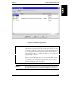
4. The interface shows the current status of each PCI Hot Plug slot. Next to
the name of each slot are graphic representations of two LEDs, one green
and one amber. These show the same reading as the slot’s LEDs on the
I/O baseboard. Table 6-1 shows the meaning of these LEDs.
Table 6-1. Reading Hot Plug PCI Slot LEDs to Determine Slot Status
Green
LED
Amber
LED
Indicates This Status
On Off Power to the slot is on, and the slot is operating
normally. Do not remove the board from the slot.
On On Power to the slot is on, but the slot needs attention.
Do not remove the board from the slot.
Off On Power to the slot is off, and the slot needs attention.
You can remove the board from this slot.
Off Off Power to the slot is off. You can remove the board from
this slot.
NOTE If you have a non-hot-plug board in one of the hot-plug slots,
the board will show up on the interface. But the interface will
not allow you to power down the board’s slot.
5. To select a slot, click on its listing in the window with the left mouse
button.
6. Now click on the selected slot with the right mouse button. A small
pop-up menu appears with several selections. Click on the selection
"Power." The program then asks you to confirm your selection. Do so.
7. Wait about 15 seconds. The green Power LED in the window will go dark.
Now look at the physical LEDs for this slot on the I/O baseboard. The
green LED should also be off.
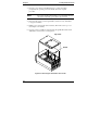
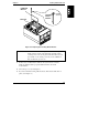
8. Unscrew the special Hot Plug board bracket from the inside of the server’s
rear panel. Then lift out the board. See Figure 6-3.
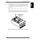
9. Lower the replacement board into the server. Push it down into the slot
connector on the I/O baseboard (See Figure 6-5).