HP NetServer LXr 8000 PCI Card Installation and Replacement and Hot-Plug Operations (revised March 1999) (this addendum replaces Chapter 6 of the HP NetServer LXr 8000 Installation Guide, October 1998) HP Part Number 5969-2119 Printed in March 1999 '"&#&( &'
Notice The information contained in this document is subject to change without notice. Hewlett-Packard makes no warranty of any kind with regard to this material, including, but not limited to, the implied warranties of merchantability and fitness for a particular purpose. Hewlett-Packard shall not be liable for errors contained herein or for incidental or consequential damages in connection with the furnishing, performance, or use of this material.
Chapter 6 Addendum HP NetServer LXr 8000 Installation Guide Introduction This chapter describes how to install I/O accessory boards into the HP NetServer LXr 8000’s I/O baseboard. The LXr 8000 supports ten PCI board slots and one ISA board slot shared with the first PCI slot. Slots P1 through P6 are reserved for accessory boards without the hot-plug compliant drivers. Slots P7 through P10 are reserved for PCI accessory boards using the PCI Hot-Plug (PHP) option and hot-plug-compliant drivers.
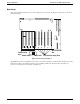
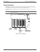
Chapter 6 Addendum HP NetServer LXr 8000 Installation Guide Boot Priority This section details the NetServer’s boot order by highest to lowest priority. See Figure 6-1 and the boot order list on the following page. 10 9 8 PCI Hot-Swap Slots Amber LED 7 6 5 4 3 2 1 Shared PCI/ISA Slot Green LED PCI (Non-Hot Swap) Slots Figure 6-1. Boot Priority Sequence The HP NetServer’s boot order (BIOS search order for a boot drive) should be considered when selecting a slot on the I/O baseboard.
Chapter 6 Addendum HP NetServer LXr 8000 Installation Guide By default the NetServer searches for boot devices in this order: 1. IDE CD-ROM drive 2. Flexible (Floppy) disk drive 3. PCI Slot P1 4. SCSI A bus ◊ SCSI device ID 0 ◊ SCSI device ID 1 ◊ SCSI device ID 15 5. SCSI B bus ◊ SCSI device ID 0 ◊ SCSI device ID 1 ◊ SCSI device ID 15 6. PCI slot 2 7. PCI slot 3 8. PCI slot 4 9. PCI slot 5 10. PCI slot 6 11. PCI slot 7 12. PCI slot 8 13. PCI slot 9 14.
Chapter 6 Addendum HP NetServer LXr 8000 Installation Guide I/O Baseboard All accessory boards plug into the I/O baseboard at the rear of the server’s chassis. The I/O Baseboard supports the following accessory board types in the respective slots. See Figure 6-2. • IDE and SCCI interface connectors – These interfaces provide the connections for the CD-ROM, floppy disk drives, and hard drives used in the NetServer.
Chapter 6 Addendum HP NetServer LXr 8000 Installation Guide Remote Control Card The HP TopTools Remote Control card must be in slot 2 and requires a cable connection to I/O baseboard. The TopTools Remote Control cable connects to the I2C connector J1D1 on the I/O baseboard. For more information on use of the Remote Control card, see Server Management for the LXr 8000. See Figure 6-2.
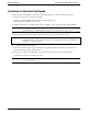
Chapter 6 Addendum HP NetServer LXr 8000 Installation Guide Installation for Non-Hot-Plug Boards Use this procedure to install all accessory boards, including PCI boards, for all of the following situations: • All new accessory boards (slots P1 through P10) • All accessory boards installed or removed in non-hot-plug-capable slots (P1 through P6), including the I/O riser card • All PCI boards with non-compliant hot-plug drivers installed or removed in hot-plug slots (P7 through P10) NOTE These steps also
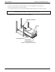
Chapter 6 Addendum HP NetServer LXr 8000 Installation Guide 5. At the front of the NetServer, extend the anti-tip foot out of the installation rack. See Figure 6-3. 6. Remove the bezel from the front of the NetServer. 7. Use a T-25 screwdriver to remove the screws holding the NetServer’s flanges to the rack front columns. CAUTION 8. To prevent damage to cables or a disruption in service due to a disconnection of cables, check for short cables at the rear of NetServer and disconnect before proceeding.
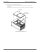
Chapter 6 Addendum HP NetServer LXr 8000 Installation Guide 9. Determine which covers to remove from the NetServer. ◊ If installing a board in slots P7-P10 only, lift off the hot-plug access panel covering these slots. See Figure 6-4. ◊ If installing a board in slots P1-P6, you must remove the Top Cover and the Shield. See Figure 6-4. Top Cover Hot Plug Access Panel Shield Figure 6-4.
Chapter 6 Addendum HP NetServer LXr 8000 Installation Guide 10. Consider the boot priority before any installing any accessory board. If installing a SCSI controller board, the controller’s priority (BIOS search order for a boot drive) is set by the board’s slot location. For details, refer to the section "Boot Priority" earlier in this chapter. 11. Identify the desired slot, before installing the accessory board. See Figure 6-5.
Chapter 6 Addendum HP NetServer LXr 8000 Installation Guide 14. Align the board along its slot and position it in the slot. 15. Push the board down into its connector on the I/O baseboard. Figure 6-6. Installing the Accessory Board 16. Insert the screw in the accessory board’s bracket and secure it to the HP NetServer’s rear panel. See Figure 6-6. 17. If the installed accessory board requires a connection to the I/O baseboard, system board, or chassis, ensure that the cable is properly attached.
Chapter 6 Addendum HP NetServer LXr 8000 Installation Guide Press in the release latch on each slide and push the server into the rack Flanges Figure 6-7. Sliding the NetServer Back into the Rack 22. Reconnect any cables you may have removed, including cables to the accessory boards, before continuing. 23. If all installation work is complete, return power to the NetServer according to the respective NOS power up instructions. 24.
Chapter 6 Addendum HP NetServer LXr 8000 Installation Guide Hot-Plug Replacement (Windows NT) Use this section for Microsoft Windows NT 4.0 PCI Hot-Plug (PHP) replacement. The procedures listed under this section provide the steps to power off/on the PCI Hot-Plug slots before removing and replacing a PCI Hot-Plugcapable board. If the PCI board is not hot-plug-capable, refer to the section in this chapter, "Installing Non-Hot-Plug Boards," for the procedure to remove and replace the board.
Chapter 6 Addendum HP NetServer LXr 8000 Installation Guide Figure 6-8. PCI Hot-Plug Utility 3. If Unsupported appears under Board in the utility’s window instead of the desired PCI board, one of the following conditions might be true: ◊ The PCI Hot-Plug board is not supported by a hot-plug compliant software driver. ◊ The software driver for the PCI Hot-Plug board is not properly installed and loaded. See Windows NT Help for loading drivers. ◊ The PCI board may be defective. NOTE 4.
Chapter 6 Addendum HP NetServer LXr 8000 Installation Guide PCI Hot Plug Slots(P10-P7) Standard PCI Slots(P6-P1) ISA or PCI Slot(P1) Figure 6-9. PCI Slot Locations (Rear view) 10 9 8 PCI Hot-Swap Slots Amber LED 7 6 5 4 3 2 1 Shared PCI/ISA Slot Green LED PCI (Non-Hot Swap) Slots Figure 6-10.
Chapter 6 Addendum HP NetServer LXr 8000 Installation Guide Powering Down the PCI Slot 1. Select the desired PCI slot (slot P9) to change by pointing to it with the mouse cursor. See Figure 6-11. 2. Left-click the desired slot (slot P9) with the mouse. Figure 6-11. PCI Hot-Plug Utility – Turn Power Off CAUTION Turning off power to any slot will render all devices or services associated with the board in the unavailable while power is turned off to the slot. 3.
Chapter 6 Addendum HP NetServer LXr 8000 Installation Guide Figure 6-12. Pop-up Menu 4. Confirm your selection by clicking Yes. As soon as confirmation is complete, the Power LED (left) on the Utility screen turns off (gray) and the slot status changes from Normal to Not Ready. The corresponding green LED on the I/O Baseboard turns off. This means power to this slot is turned off. See Figure 6-13.
Chapter 6 Addendum HP NetServer LXr 8000 Installation Guide Figure 6-13. PCI Hot-Plug Utility – Power Turned Off 5. If the Power LED in the Hot-Plug Utility window stays green, then consider these steps: a. Re-install the software driver and then repeat this procedure. Refer to the Windows NT Help file to re-install the driver. b. Power down the NetServer, re-seat the PCI board, power the system up, and then repeat Steps 2 to 4 in this procedure. c.
Chapter 6 Addendum HP NetServer LXr 8000 Installation Guide Removing a PCI Hot-Plug Board Use this procedure to physically remove a PCI Hot-Plug Board from the slot. 1. At the front of the NetServer, extend the anti-tip foot out of the installation rack. See Figure 6-14. 2. Remove the bezel from the front of the NetServer. 3. Use a T-25 screwdriver to remove the screws holding the NetServer’s flanges to the rack front columns.
Chapter 6 Addendum 5. HP NetServer LXr 8000 Installation Guide Use a T-25 screwdriver to remove only the PCI Hot-Plug Access Panel. See Figure 6-15. Screws(2) Hot Plug Access Panel Rear of Chassis Figure 6-15. Removing Hot-Plug Access Panel CAUTION DO NOT DROP SCREWS OR OTHER METAL OBJECTS INTO THE SYSTEM.
Chapter 6 Addendum HP NetServer LXr 8000 Installation Guide 6. Verify power to the desired PCI slot is turned off, by checking the two LEDs associated with the desired PCI slot. The green Power LED must be OFF. See Figure 6-16 and Table 6-1. PCI Hot-Plug LEDs Figure 6-16. Hot-Plug Slots and LEDs The following table decodes the LEDs for each PCI slot: Table 6-1. PCI LED Power Code 20 Green LED Amber LED On Off Power to the slot is on, and the slot is operating normally.
Chapter 6 Addendum NOTE HP NetServer LXr 8000 Installation Guide If you have a non-PCI Hot-Plug board in one of the PCI Hot-Plug slots, the PCI board will show up on the NOS software utility’s display. But the NOS utility will not allow you to power down the PCI board's slot. 7. If not, go back to the PCI Hot-Plug utility and verify you have turned off power to the correct slot. 8.
Chapter 6 Addendum HP NetServer LXr 8000 Installation Guide 13. Grasp the edge of the PCI board firmly and pull upward. See Figure 6-17. Try to pull the board straight up without wiggling it side to side along the length of the board. Accessory Board Bracket Figure 6-17. Removing PCI Boards 14. Refer to the section in this chapter, "Replacing a PCI Hot-Plug Board," to install a new or replacement but identical PCI Hot-Plug board in the PCI Hot-Plug slot.
Chapter 6 Addendum HP NetServer LXr 8000 Installation Guide Replacing a PCI Hot-Plug Board Use this procedure to physically replace a PCI Hot-Plug Board. The following conditions must be met before replacing a PCI Hot-Plug Board: • The desired PCI Hot-Plug slot must be powered off. • The replacement PCI Hot-Plug board must be identical to the board it replaces. • The replacement PCI board must use the same hot-plug driver. • The replacement PCI board must be a 32-bit or 64-bit PCI Hot-Plug board.
Chapter 6 Addendum HP NetServer LXr 8000 Installation Guide Accessory Board Bracket Figure 6-18. Replacing PCI Boards 6. Ensure the board is fully seated before continuing. 7. Insert the screw into the PCI board’s bracket and use the T-15 driver or Phillips screwdriver to secure it to the rear panel. See Figure 6-18. 8. If the previous PCI board had a cable(s) attached to it, connect the cable(s) to the new board before continuing. 9.
Chapter 6 Addendum HP NetServer LXr 8000 Installation Guide PowerIng Up the PCI Slot Use this procedure to apply power to a hot-plug slot only after replacing an existing PCI Hot-Plug board with an identical PCI Hot-Plug board. 1. If not already open, select the PCI Hot-Plug Utility from the Programs menu. 2. Left-click the PCI slot (Slot 9) with the Not Ready status. Figure 6-19. PCI Hot-Plug Utility – Turn Power On 3. Click the Power button in the upper right of the menu. See Figure 6-19.
Chapter 6 Addendum HP NetServer LXr 8000 Installation Guide Figure 6-20. Pop-up Menu 4. Confirm your selection by clicking Yes. The pop-up prompt should disappear and the Power LED (left) for the slot (slot 9) should turn green and after a few seconds the status should change from Not Ready to Normal. See Figure 6-21. 5. If the Power LED (left) turns green, wait several seconds for the software driver to initialize the PCI board and then observe the Attention LED (right) and the board status.
Chapter 6 Addendum HP NetServer LXr 8000 Installation Guide Figure 6-21. PCI Hot-Plug Utility – Power Turned On 6. If the right LED (Attention) stays amber or goes to amber in the Hot-Plug Utility window or on the I/O baseboard, then consider these steps: a. Power down the slot as described in Steps 2 to 5 of the section in this chapter, "Powering Down the PCI Slot," and then re-seat the PCI board. b. Re-install the software driver and then repeat this procedure. c.
Chapter 6 Addendum HP NetServer LXr 8000 Installation Guide 10. If all desired PCI Hot-Plug boards have been installed, replace the PCI Hot-Plug Access Panel. See Figure 6-22. Hot Plug Access Panel Figure 6-22. Replacing the Hot-Plug Access Panel 11. Use the T-25 driver to secure the hot-plug access panel to the top cover with the two screws.
Chapter 6 Addendum CAUTION HP NetServer LXr 8000 Installation Guide To prevent damage to cables, or a disruption in service due to a disconnection of cables, use caution when sliding the chassis into the rack. 12. If chassis work is complete, slide the NetServer chassis back into the rack. See Figure 6-23. Press in the release latch on each slide and push the server into the rack Flanges Figure 6-23. Siding the NetServer Back into the Rack 13.