HP NetServer LXr Pro8 200 MHz/1 MB Processor Board Upgrade Guide HP Part Number 5967-2101 Printed in January 1998
Notice The information contained in this document is subject to change without notice. Hewlett-Packard makes no warranty of any kind with regard to this material, including, but not limited to, the implied warranties of merchantability and fitness for a particular purpose. Hewlett-Packard shall not be liable for errors contained herein or for incidental or consequential damages in connection with the furnishing, performance, or use of this material.
Contents 1 Overview.......................................................................................................1 About This Guide ...........................................................................................1 Additional Information ................................................................................1 Verify Contents ..............................................................................................1 Tools Required...............................................
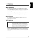
1 Overview About This Guide This guide describes the installation of the 200 MHz/1 MB Processor Board Accessory Kit in HP NetServer LXr Pro8 systems. The processor board includes two 200 MHz/1 MB CPU chips, on which two heat pipes are mounted for efficient cooling. Use this guide to install up to three additional processor boards in a system that already has one 200 MHz/1MB processor board installed. In addition to the installation instructions, this guide contains regulatory information.
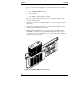
Chapter 1 Overview 1. Processor board, shown in Figure 1-1, has the following parts mounted on it: • Two 200 MHz/1 MB CPU chips • Two heat pipes • Two VRMs (voltage regulator modules) Be sure to keep the bag around the processor board sealed until you are ready to install the board. 2. HP NetServer LXr Pro8 200 MHz/1 MB Processor Board Upgrade Guide (this guide). 3. Update Return Kit that explains how to return unused terminator boards to HP for environmentally safe disposal. 4. HP Navigator CD-ROM.
Chapter 1 Overview Tools Required • An antistatic service kit (3MTM 8501/8502/8503 or equivalent). This kit includes a static-dissipating work surface, a chassis clip lead, and a wrist strap. • Number 2 Phillips head screwdriver.
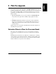
2 Plan the Upgrade Up to four processor boards, each with two 200 MHz/1 MB CPU chips, can be installed in the HP NetServer LXr Pro8 system. All four processor board slots on the system board must be filled, even when fewer than four processor boards (eight CPUs) are installed. Each processor board slot must contain one of two kinds of boards: • Processor board. The processor board contains two 200 MHz/1MB CPU chips with two heat pipes and two VRMs (voltage regulator modules). or • Terminator board.
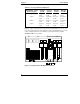
Chapter 2 Plan the Upgrade Table 2-1.
3 Perform the Upgrade The installation steps are as follows: 1. Power down the HP NetServer. 2. Slide out the satellite chassis. 3. Lift and remove the cover of the satellite chassis. 4. Remove the terminator board. 5. Install the processor board. 6. Slide the satellite chassis back into place. CAUTION The processor board and CPU chips are sensitive to static electricity, and can be easily damaged by improper handling.
Chapter 3 Perform the Upgrade Figure 3-1. HP NetServer Control Panel 3. Unlock the power interlock switch at the back of the HP NetServer by turning it clockwise as shown in Figure 3-2. This turns off DC power to the satellite and unlatches the satellite chassis. Figure 3-2.
Chapter 3 NOTE Perform the Upgrade After you unlock the power interlock switch, there is no power present at any internal or externally accessible area of the satellite chassis. However, five volts of power are present at the power supply pins on the base chassis where the satellite attaches. To remove all power, unplug the AC power cord. Slide Out the Satellite Chassis CAUTION Wear a wrist strap and use a static-dissipating work surface connected to the chassis when handling components.
Chapter 3 Perform the Upgrade Figure 3-3. Location of the Retention Bracket 4. Stand behind the HP NetServer and grasp the two ejector handles on the rear panel. Pull both handles down firmly, and then pull the satellite chassis toward you. Pull it out until its slides are fully extended as shown in Figure 3-4. The slides lock in the extended position so that the satellite chassis cannot move.
Chapter 3 Perform the Upgrade Figure 3-4. Slide Out Satellite Chassis Lift and Remove Top Cover of Satellite Chassis 1. Find the fingerholds on the cover of the satellite chassis. 2. Place a finger in each of the two fingerholds and push both fingerholds toward each other. 3. Maintain pressure with your fingers and slide the cover away from you. The cover slides about one-half inch before stopping. 4. Lift the cover by the fingerholds until it is fully open.
Chapter 3 Perform the Upgrade Figure 3-5. Satellite Chassis with Open Cover 5. Pull back one of the spring-loaded hinge pins on the underside of the cover and lift the cover off. 6. Set the cover aside. Looking down into the satellite chassis, you can see the processor and terminator boards on the system board. Remove the Terminator Board 1. Determine which terminator board (or boards) you will be removing from your system.
Chapter 3 Perform the Upgrade Figure 3-6. Processor and Terminator Boards on the System Board 2. Using a Phillips head screwdriver, unscrew the two mounting screws that secure the terminator board in place. 3. Grasp the board you are removing, and lift firmly. Place it on the antistatic mat. 4. If you are installing more than one 200 MHz/1MB processor board, remove additional terminator boards as necessary.
Chapter 3 Perform the Upgrade Figure 3-7. Remove the Terminator Board 5. You may return the terminator boards you removed to Hewlett-Packard for environmentally safe disposal. To return used boards, see the Update Return Kit.
Chapter 3 Perform the Upgrade Install the Processor Board 1. Remove the processor board from the sealed bag. NOTE Do not change the jumper settings on the processor board. These settings are factory set. 2. Install the processor board in the slot from which you removed the terminator board. Gently, but firmly push the board into place. You must install one processor board for every terminator board that you removed. 3. Using a Phillips head screwdriver, secure the mounting screws in place.
Chapter 3 Perform the Upgrade Figure 3-8. Unlock the Slides 4. Grasp the ejector handles and push the satellite chassis all the way forward until it locks into position against the base chassis. Be careful to keep the ejector handles in the "down" position. 5. Push the ejector handles up until they stop. You should hear a click. 6. Replace the retention bracket as shown in Figure 3-3. 7. Reconnect any cables to PCI cards you might have disconnected earlier.
Chapter 3 Perform the Upgrade Figure 3-9.
A Warranty and Support The hardware warranty below applies to components purchased as accessories. If your component was factory installed as part of an HP NetServer model, refer to the warranty statement provided with your system documentation. Hardware Warranty This HP NetServer accessory is covered by a limited hardware warranty for a period of one year from receipt by the original end-user purchaser.
B Regulatory Information Notice for USA: FCC Radio Frequency Emissions Statements Class A Product Statement This equipment has been tested and found to comply with the limits for a Class A digital device, pursuant to Part 15 of the FCC Rules. These limits are designed to provide reasonable protection against harmful interference when the equipment is operated in a commercial environment.
Appendix B Regulatory Information Notice for EU DECLARATION OF CONFORMITY according to ISO/IEC Guide 22 and EN 45014 Manufacturer’s Name: Hewlett-Packard Company Manufacturer’s Address: 5301 Stevens Creek Blvd.
Index A Antistatic service kit, 3, 9 R Regulatory information, 21 C Contents of package, 1 CPU buses A and B, 5 S Satellite chassis removing top cover, 11 sliding it back into place, 15 sliding it out, 9 H Hardware warranty, 19 HP Navigator CD-ROM, 2, 15 P Power down procedure, 7 Power interlock switch, 8, 17 Processor board, 2, 5, 6, 13, 15 T Terminator board, 5, 6, 12, 13 U Update Return Kit, 2, 14 23