HP NetServer Product Line Service Reference Guide Volume 3 High-End Version 1 Last Updated: February 2000
Notice The information contained in this document is subject to change without notice. Hewlett-Packard makes no warranty of any kind with regard to this material, including, but not limited to, the implied warranties of merchantability and fitness for a particular purpose. Hewlett-Packard shall not be liable for errors contained herein or for incidental or consequential damages in connection with the furnishing, performance, or use of this material.
Table of Contents HP NetServer LX Front Panel Controls Covers Exploded Views HP NetServer LX Pro and LXe Pro Parts List Footnotes HP NetServer LX Keyboards HP NetServer LX Power Cords Mass Storage Cables System Board System Board Connectors System Switches and Jumpers Cabinet and Redundant Power Supply Power Supply Status LED Display Memory Model A SIMMs Model B SIMMs DIMMs Video Memory - DRAM Boot Device Priority Cabling Configurations Hot Swap Subsystem SCSI Address Settings LXe Cabling Configurations LXe
Covers Memory Single Memory Board Dual Memory Boards Memory Capacity Boot Device Priority I/O Baseboard Processor Baseboard Processor Baseboard Jumper Settings IRQ Settings PCI Hot Plug Boards Exploded Views Parts List Specifications Video Resolutions BIOS Video Resolutions HP NetServer LXr Pro System Views Front View Rear View Covers Memory Accessory Boards Boot Device Priority Processors Exploded Views Parts List Keyboards Power Cords System Board Jumper Settings Specifications HP NetServer LXr Pro8 Syste
System Board System Switches Specifications 103 104 104 Notes 107 Index 111 v
HP NetServer LX Front Panel Controls Reset Power on Switch Switch Disk Access LED Fan LED NetServer Status LCD Front Panel Keyboard Lock Switch Control Power Supply LED Front Panel Key Lock Description Power on Switch Turns NetServer power on and off. Press once to turn it on; press again to turn it off. Reset Switch Resets all processors and reboots the system, as if the power was cycled off and on, except that the mass storage devices do not powercycle.
Power Supply Status LED Definition LED color One PSM Two PSMs Three PSMs Green OK OK OK Yellow Red Power cage temperature warning Power cage temperature warning Power cage temperature warning, or one PSM LED indicator is red or yellow Power cage temperature is critical, or one PSM LED indicator is red or yellow Power cage temperature is critical, or one PSM LED indicator is red or yellow Power cage temperature is critical, or two PSM LED indicators are red or yellow Cooling Fan Status LED De
Lumber or other spacer 3
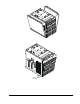
Processor and memory board cooling duct cover CAUTION Do not force the cover down onto the boards. Forcing the cover may result in damage to the NetServer. Damage due to improper board installation is not covered by the warranty.
EISA/PCI Board Retainer Exploded Views 5
23 24 25 22 26 27 28 30 29 6
37 31 31 32 36 35 33 34 LXe Pro 39 HP NetServer LX Pro and LXe Pro Parts List NOTE The part numbers in the list were those available at the time of publication. Part numbers may change after publication. HP's parts price list database will generally contain a reference to the revised part number. If a system board needs to be replaced, remove processor board, video DRAM, and any added accessory boards, and keep them with the server under repair.
Fig 8 Description Replacement Exchange 8 Hot Swap Assy-Filler Panel 5063-8391 9 Filler Panel 5063-8389 10 1.44MB Floppy ( a ) D2035-631212 11 CD-ROM Drive D2992-63004 12 Tray - CD-ROM C2260-00025 13a 2.1GB SCSI-2 HDD 5400 D2077-63100 13b 2.
Fig Description Replacement * Heat Sink/Clip 5064-0752 (assy) * Heat Sink or use 5064-0752 (assy) 5182-9343 * PCI DAC Fast/Wide C3610-63050 * Adapter, SCSI 5182-4550 * Cable, Flex Disk Data (F11) 5182-6735 * Cable, SCSI, Term 50-pin C11 5182-6748 * Cable, SCSI, Term 50-pin, long (C21) 5182-9413 * Cable, SCSI, Bridge 68-pin (C14) 5182-6747 2 Exchange C3610-69050 * Cable, I C Management Bus 400mm (B11) 5182-6730 * Cable, SCSI, Port 68-pin (C13) 5182-6740 * Cable, SCSI, 500
( c ) Terminator board must be installed when there is only 1 processor board in the system. ( d ) Early machines use several small single-slot panels. ( e ) This fan jumper must be installed on the system board. ( f ) Replace all A rev 64MB SIMMs with B rev parts. ( g ) This part number is constantly revised for each new release. When you order using this number you will be sent the current revision of the CD-ROM. ( h ) Price list points from this part number to current part number.
HP NetServer LX Keyboards Language HP Part Number Product No. Option Language United States C1405-61301 #ABA Dutch C1405-61306 #ABH French C1405-61305 #ABF Czech C1405-61336 #AKB Danish C1405-61316 #ABY German C1405-61303 #ABD Russian C1405-61330 #ACB Spanish C1405-61304 #ABE Japanese C3755-60224 #ABJ Fr.
Turkish C1405B #AB8 8120-5394 AB8 Portugal C1405B #AB9 8120-5394 AB9 Russia C1405B #ACB 8120-5394 ACB Denmark C1405B #ABY 8120-5394 ACE Japan C1405B #ABA 8120-5400 ACF Norway C1405B #ABN 8120-5394 ACK Belgium C1405B #ABW 8120-5394 ACO Arabic/English C1405B #ABV 8120-5394 ABV South Africa/India C1405B #ABA 8120-5399 ACQ Sweden C1405B #ABS 8120-5394 ACY Czech C1405B #AKB 8120-5394 AKB Hungarian C1405B #AKC 8120-5394 AKC Polish C1405B #AKD 8120-5394 AKD Mass
System Board PCI Bus 1:P1 P2 P3 PCI Bus 0: P4 P5 Unused P6 S6A1 Switch J6A1 Jumpers Video DRAM Monitor Parallel Port Serial Ports Keyboard / Mouse EISA/ISA Bus: E1 E2 E3 E4 Video Cirrus Power Supply (14 Pin) Battery/Real Time Clock Power Supply (20 Pin) Memory Slot Flexible Disk Drive SCSI AIC 7880 SCSI Bus B IDE Disk Drive SCSI AIC 7880 Unused Control Panel SCSI Bus A HD LED Unused HD LED Fan 4 Fan 3, 2, 1 Loopback connector Processor Slot 1 Processor Board 2 or Terminator Board System
Connector Name Connector Label Connector Name Connector Label Processor Slot 2 J7D1 Processor Slot 1 J6D1 Fan 1 Fan 2 Fan 3 J5G3 J5G2 J2G4 Fan 4 (loop back connector installed) J2G3 HD LED1 J5G1 HD LED J2G1 I2C J2G SCSI-A J1G1 SCSI-B J1F1 Unused J5E1 Unused J4G1 Unused J5A1 Unused J8G1 Unused J2A3 System Switches and Jumpers Always refer to the Technical Reference Label for the latest settings for any jumpers and switches.
Cabinet and Redundant Power Supply The chart below explains the power supply and processor board configurations for the LX Pro and LXe Pro systems.
Power Supply Status LED Display The Front Panel Power Supply Status LED display is controlled by the Power Supply Redundancy (or Mode) switch and displays real-time power supply status. The table below shows the correlation between the statuses of individual power supply modules and the Front Panel LED indicators. Front Panel Power Supply Status LED Definitions Front Panel LED Color Power Status Green Power system OK Yellow Power system functioning.
• Size SIMMs installed in Bank 1 Model A Model B Size SIMMs permitted in Bank 2 Size SIMMs permitted in Bank 2 16 MB 16 MB or 32 MB 16 MB, 32 MB, 64 MB, or 128 MB 32 MB 16 MB or 32 MB 16 MB, 32 MB, 64 MB, or 128 MB 64 MB 64 MB or 128 MB 16 MB, 32 MB, 64 MB, or 128 MB 128 MB 64 MB or 128 MB 16 MB, 32 MB, 64 MB, or 128 MB Only these memory configurations are supported: SIMM size #1 SIMM size #2 4-SIMM Configuration 8-SIMM Configurations 16-SIMM Configurations 17
Model B SIMMs A Model B SIMM memory board has 16 sockets, each of which may contain a 16 MB, 32 MB, 64 MB, or 128 MB SIMM. For model B SIMMs, you can mix any two sizes from 16 MB, 32 MB, 64 MB, or 128 MB SIMMs in Bank 2. Key in Socket Retaining latch Bank 2 Bank 1 Notch on SIMM Follow these rules when installing memory on this board: • Use only 60 ns HP SIMMs listed on the Product Reference Label, which is located on the side of the HP NetServer chassis.
One SIMM size Two SIMM sizes Choose two of the following SIMM sizes: 16, 32, 64 or 128 SIMM size #1 SIMM size #2 4-SIMM Configuration 8-SIMM Configuration 8-SIMM Configuration 16-SIMM Configuration 16-SIMM Configuration 19
Supported Memory Configurations The following HP SIMMs are supported: SIMM Type HP Part Number 16 MB SIMM D4891A-69001 32 MB SIMM D4892A-69001 64 MB SIMM D4290A-69002 128 MB SIMM D4893A-69001 DIMMs The 4 GB memory board, which uses DIMMs (Dual In-Line Memory Modules), replaces the existing SIMMbased memory that is part of the original configuration of HP LX and LXe NetServers. The 4 GB memory board enables the installation of as few as 512 MB or as many as four GB.
Optional Memory Configurations for 4 GB Memory Board Video Memory - DRAM The on-board video circuitry supports several screen resolutions. Increasing the video memory buffer size to 1 MB allows the controller to support 132-column text mode and high resolution graphics mode. Expand video memory by installing a 256 K x 16 (512 KB), 70 Ns, 40-pin SOJ package DRAM IC. Obtain this memory IC from a local electronics supplier. For the Model A, the video RAM chip is not standard. The part number is 5182-9404.
Duplex, Non-Disk Array Model using the Internal Controller * C11 * SCSI or IDE B1 Device B2 C11 SCSI or IDE Device System Board C12 SCSI or IDE Device Left cages Rear view C12 SCSI A * Termination resistor incorporated into cable SCSI B Default Switch Settings Off Upper Right Cage Lower Right Cage 1 2 3 4 5 6 1 2 3 4 5 6 On 1 2 3 4 5 6 1 2 3 4 5 6 Rear view 22 CD-ROM C14 Right cages Rear view IDE A1 A2 C14 Flexible disk Flexible Disk Upper Left Cage Shelf # L1 L2 L3 R1 R2 R
Non-Duplex, Disk Array with PCI Controller Board * SCSI or IDE B1 Device B2 C11 SCSI or IDE Device A C14 C12 Right cages Rear view IDE A1 A2 ** CD-ROM SCSI or IDE Device ** C14 Left cages Rear view C15 C15 SCSI A System Board Flexible disk Flexible Disk * Termination resistor incorporated into cable SCSI B **Backplane terminates automatically if no cable is connected Channel 1 C13 Channel 0 Rear Panel SCSI Connector PCI DAC Board Default Switch Settings Off On 1 2 3 4 5 6 1 2
Hot Swap Subsystem SCSI Address Settings Upper Cage Switch Settings 24 SCSI Address Lower Cage Switch Settings SCSI Address 3 - Off Shelf 1 = ID 1 3 - Off Shelf 4 = ID 4 4 - Off Shelf 2 = ID 2 4 - Off Shelf 5 = ID 5 6 - Off Shelf 3 = ID 3 6 - On Shelf 6 = ID 6 3 - Off Shelf 1 = ID 1 3 - Off Shelf 4 = ID 4 4 - On Shelf 2 = ID 0 4 - On Shelf 5 = ID 0 6 - Off Shelf 3 = ID 3 6 - On Shelf 6 = ID 6 3 - On Shelf 1 = ID 9 3 - On Shelf 4 = ID 12 4 - Off Shelf 2 = ID 10 4 - Off She
LXe Cabling Configurations LXe Pro: Duplex, Non-Disk Array Model using the Internal Controller CAUTION Do not attempt to run the NetServer with any mass storage devices installed in the right side (including shelves B1 or B2, illustrated above) without first installing a second power supply module.
Default Switch Settings Off On 1 2 3 4 5 6 Upper Left Cage Shelf # 1 2 3 4 5 6 SCSI ID # Lower Left Cage L1 L2 L3 1 2 3 L4 L5 L6 4 0 6 Rear view LXe Pro: Non-Duplex, Disk Array with PCI Controller Board CAUTION Do not attempt to run the NetServer with any mass storage devices installed in the right side (including shelves B1 or B2, illustrated above) without first installing a second power supply module.
Default Switch Settings Off On 1 2 3 4 5 6 Upper Left Cage Shelf # 1 2 3 4 5 6 SCSI ID # Lower Left Cage L1 L2 L3 1 2 3 L4 L5 L6 4 0 6 Rear view LXe Hot Swap Subsystem SCSI ID Settings Switch 1 and 2 3 Function 2 I C Bus Address Description Upper Left Cage: (I2C address=7) 1=Off 2=Off Lower Left Cage: (I2C address=6) 1=Off 2=Off High/Low SCSI IDs On Assigns high SCSI IDs to the cage. Determines whether the SCSI IDs used for the cage will be the lower IDs or the higher IDs.
Left upper hot swap drive cage switch settings and SCSI ID numbers Switch Position Hot Swap Drive Shelf 1 2 3 4 5 6 1 2 3 off off off off on off ID=1 ID=2 ID=3 off off off on on off ID=1 ID=0 ID=3 off off on off on off ID=9 ID=10 ID=11 off off on on on off ID=9 ID=8 ID=11 Left lower hot swap drive cage switch settings and SCSI ID numbers Switch Position Hot Swap Drive Shelf 1 2 3 4 5 6 4 5 6 off off off off on on ID=4 ID=5 ID=6 off off off
Width 425 mm (16.58 in) 425 mm (16.58 in) Depth 650 mm (25.35 in) 650 mm (25.35 in) Weight Minimum: 59 kg (131 lb) Maximum: 85 kg (187 lb) System footprint 676 x 454 mm (26.625 x 17.875 in) Keyboard Height 3.4 cm (1.4 in) Width 46.8 cm (18.4 in) Depth 19.8 cm (7.8 in) Weight 1.9 kilograms (4.2 lb) Cable Length Keyboard cable 3 m (9.
HP NetServer LXr 8000 System Information System Views Front Control Panel Power Button Reset Button Power LED Control Secure Mode LED Secure Mode Button Description Turns server power on and off. Power Button Power LED Glows steady green when power is on, and flashing green when the server is in ACPI Sleep. If the LED is dark, system power is off. Performs a hard reset. Reset Button Secure Mode Button Secure Mode LED Puts the server in Secure Mode, if your server was configured for Secure Mode.
Control Panel LCD Screen and Navigation Buttons Escape Not Used Enter Scroll Up One Line Scroll Down One Line Button Name Two-Line Display Function Return to previous menu. Escape Select an item from a menu. Enter Down Arrow Scroll down one line through the current screen or menu. Up Arrow Scroll up one line through the current screen or menu.
power supply or fan, for example), the server may still be operating. A condition exists which may cause the failure of a server component. The server is operating normally. key: = LED off = LED on = LED blinking The Main Menu By default, the HP NetServer’s control panel display shows something like this: HP LXr 8000 To reach the main menu from this default screen, press the control panel’s Enter button. The main menu appears: The menu selections are: • HW Sys Info.
FAIL (Power Supply Failure) Lights solid yellow when power supply fails. Blinks yellow when power supply is drawing more current than it should, because of a short-circuit in the power supply or elsewhere in the server. If the short is in the power supply, the power supply shuts down. If the short is in the server, the server shuts down. Communication Ports PCI Hot Plug Slot LEDs Slots P7 through P10 on the I/O baseboard are 64-bit PCI slots that can be individually powered down through system software.
Covers Screws For Hot-Plug PCI Access Cover Hot-Plug PCI Access Cover Top Cover Screws for Top Cover I/O Shield WARNING Before removing the top cover, always disconnect the power cord and unplug telephone cables. Disconnect the power cord to avoid exposure to high energy levels that may cause burns when parts are short-circuited by metal objects such as tools or jewelry. Unplug telephone cables to avoid exposure to shock hazard from telephone ringing voltages.
• For board-to-board interleaving, each memory board must hold the same number of DIMMs. If one board holds two types of DIMMs, the other board must also, and in the same banks. (For example, if one memory board holds eight 256 MB DIMMs in Banks A and B and eight 64MB DIMMs in Banks C and D, the other board must match this configuration exactly if card-to-card interleaving is to take place.
The Primary and Secondary Memory Boards Bank A Bank B J1 J1 J2 J2 J5 J5 J6 J6 J9 J9 J10 J10 J13 J13 J14 J14 J3 J3 J4 J4 J7 J7 J8 J8 J11 J11 J12 J12 J15 J15 J16 J16 Bank C Bank D J1 J1 J2 J2 J5 J5 J6 J6 J9 J9 J10 J10 J13 J13 J14 J14 J3 J3 J4 J4 J7 J7 J8 J8 J11 J11 J12 J12 J15 J15 J16 J16 DIMM Slot Numbers and Bank Numbers 37
Key: Bank A Bank C Bank B Bank D P rim a ry B o a rd S e c o n d a ry B o a rd J1 J1 J2 J2 J5 J5 J6 J6 J9 J9 J10 J10 J13 J13 J14 J14 J3 J3 J4 J4 J7 J7 J8 J8 J11 J11 J12 J12 J15 J15 J16 J16 B o a rd -to -B o a rd In te rle a v in g : 8 D IM M S P rim a ry B o a rd S e c o n d a ry B o a rd J1 J1 J2 J2 J5 J5 J6 J6 J9 J9 J10 J10 J13 J13 J14 J14 J3 J4 J7 J8 J11 J12 J15 J16 J3 J4 J7 J8 J11 J12 J15 J16 B o a rd -to -B o a rd In te rle a v in g : 1 6 D IM M
Key: Bank A Bank B Bank C Bank D Primary Board Secondary Board J1 J2 J5 J6 J9 J10 J13 J14 J1 J2 J5 J6 J9 J10 J13 J14 J3 J4 J7 J8 J11 J12 J15 J16 J3 J4 J7 J8 J11 J12 J15 J16 Board-to-Board Interleaving: 24 DIMMS Primary Board Secondary Board J1 J2 J5 J6 J9 J10 J13 J14 J3 J4 J7 J8 J11 J12 J15 J16 J1 J2 J5 J6 J9 J10 J13 J14 J3 J4 J7 J8 J11 J12 J15 J16 Board-to-Board Interleaving: 32 DIMMS DIMM and 32-DIMM Configuration for Interleaved Memory Boards Boot Device Priority NOTE Plugging the HP TopT
On-board SCSI consists of two channels, A and B. Channel A controls the HP NetServer's internal hard disk drives. Channel B handles the server's external SCSI port. On each SCSI channel, the server scans for a boot device starting at device ID 0 and works up from there. Hot Replacement of PCI Hot Plug Boards To replace one PCI Hot Plug board with another while the server is running, you must: • Turn off power to the slot through your server’s NOS. If you are a Windows NT 4.
Exploded Views 5 6 4 8 3 2 9 1 15 16 17 18 19 20 14 13 21 12 22 11 23 41
34 35 33 36 32 31 30 29 28 27 26 25 24 Parts List Fig 42 Description Replacement 5064-6607 Exchange 1 750W Power Supply Module 5064-6608 2 I/O Baseboard tray 3 I/O Baseboard PCA D6021-63004 4 I/O Riser PCA D6021-63007 5 Remote Control Board D6028-63001 6 Top Cover Assembly w/label D6021-63059 8 Non-Hot-Plug PCI Board Cover Not orderable 9 Chassis Not orderable 11 CD-ROM Drive, Slimline 12 Peripheral Bay Chassis 13 Peripheral Bay Backplane PCA 14 Peripheral Bay Cove
Fig Description Replacement Exchange 17 Memory PCA D6021-63005 D6021-69005 18a DIMM, 64 MB, 50ns D6112-63000 D6112-69000 18b DIMM, 256 MB, 50ns D6114-63000 D6114-69000 19 3.5 Floppy Drive, Slimline D6021-63041 20 Hot-Swap Filler Panel, Low-Profile 5064-4689 21a SCSI Ultra2 HDD, 4.
Fig Description Replacement * Bezel Kit for HP Rack Enclosures D6021-63043 * Bezel Kit, for 3rd Party Rack Enclosures D6021-63061 * Ejector Handles, CPU (Kit) D6021-63044 * Battery, Remote Control PCA 5183-6570 * Hot-Plug PCI Slot Cover Bracket D6021-63063 * Bezel, LCD Display (HP) D6021-63064 * Bezel, LCD Display (non-HP) D6021-63065 * Battery, I/O baseboard, type CR 2032 * This part is not on an exploded view.
I/O Baseboard Jumper Settings Default Jumper Settings A B C Update BMC Code 1 No Operation BIOS Recover 2 Normal Boot Spare Jumper 3 Spare Jumper Flash VPP=No Write 4 FlashVPP = +12V CMOS CLEAR 5 No Operation Clear CMOS Password 6 No Operation PHP Switch Override 7 No Operation Enable SPI Chain 8 No Operation Processor Baseboard VRM 2 VRM 6 VRM 1 VRM 4 VRM 5 Jumper Block J31 VRM 3 Processor 1 Front of NetServer Processor 2 Processor 3 Processor 4 45
Number of Processors Install Processor in These Slots Terminators Required for These Slots Voltage Regulator Modules Required in These Slots 1 Proc 1 Proc 2 Proc 3 Proc 4 VRM 1 VRM 2 VRM 3 2 Proc 1 Proc 2 Proc 3 Proc 4 VRM 1 VRM 2 VRM 3 VRM 4 3 Proc 1 Proc 2 Proc 3 Proc 4 VRM 1 VRM 2 VRM 3 VRM 4 VRM 5 4 Proc 1 Proc 2 Proc 3 Proc 4 None VRM 1 VRM 2 VRM 3 VRM 4 VRM 5 VRM 6 Processor Baseboard Configurations for 1 Through 4 Processors Processor Baseboard Jumper Settings 1 2 Disable VRMs
Specifications Video Integrated 1024x768sx256 60-75hz Video, 1 meg video RAM (Cirrus 5446) Expansion Slots Total PCI Buses:3, Total I/O slots:10 • 4 64-bit PCI Full Length on PCI 2 (Hot Swap) • 5 32-bit PCI Full Length on PCI 1 • 1 shared 32-bit PCI/ISA Full Length on PCI 0 Dimensions System dimensions 12.25 in. high x 17.5 in. wide x 28 in. deep (31.1 cm high x 44.5 cm wide x nn 71.1 deep) Rack space 7 EIA units System weight 130 lb.
HP NetServer LXr 8500 System Views Front View Control Panel Front Control Panel Power Button Reset Button Power LED Secure Mode LED Secure Mode Button Power, Reset, and Secure Mode Buttons and LEDs NOTE A small protective cover is provided on the HP NetServer's control panel to cover the Power and Reset buttons. This cover prevents an accidental resetting or powering down of the HP NetServer during normal operation. It can also be easily opened for access to the Power and Reset buttons.
Button If sleep states are not available, then this button only turns power On or Off. The sleep states are NOS dependent and not available if your NOS does not support power management based on the ACPI standard. A NOS supporting ACPI allows this button to be configured through a user interface. Refer to "Applying Power to the HP NetServer" and "Using Sleep States". Power On/Off/ Sleep LED This LED glows a steady green when power is On, and dark, when the HP NetServer is powered Off.
Control Panel Display Control Buttons Button Name Description Return to previous menu. Escape Select an item from a menu. Enter Down Arrow Scroll down one line through the current screen or menu. Up Arrow Scroll up one line through the current screen or menu. Left Arrow Not used. Right Arrow Not used. Status LEDs Red Yellow Green Interpreting the HP NetServer Status LEDs Red LED Yellow LED Green LED Off Off Off Main power is off and the HP NetServer may or may not be on standby power.
Indicators and Controls Directly Behind the Front Bezel CD-ROM Drive Activity LED Flexible Disk Drive Activity LED Eject Button Eject Button DAT Tape Drive (Optional) Hot Swap Hard Disk Drive (Both Drives Optional) Power ON LED Activity LED Status LEDs Behind the Front Bezel Tape Drive LED Codes If the optional HP DAT tape driver is used: Left LED Right LED Definition Off Off No Power. On Off Cartridge Loaded, but No activity. Flashing* Off Cartridge Loaded and Active.
Fan Indicators The fan indicators are only visible when the fan cover is removed and each one identifies which fan is defective. #2 #1 Fan Indicators #4 #3 #6 #5 Front of NetServer Fan Indicators The Main Menu Use this topic to view and use the Main menu to make selections on the control panel LCD window. The following message (default) displays when no other activity is present on the LCD window: The menu selections are: ◊ HW Sys Info.
Rear View PCI Hot Plug latch PCI LED Indicators External SCSI Port Serial, Parallel, Monitor Ports AC Power Inlet HP TopTools Remote Control Card and Connectors #1 #2 #3 Power Supplies Rear Panel of the HP NetServer Power Supply LEDs PWR PRFL FAIL Power Supply LEDs Power Supply Module LED Descriptions Control PWR (Power) 54 Description Glows steady green when HP NetServer is powered up.
NetServer shuts down. Communication Ports Keyboard Mouse External SCSI Serial Port B Serial Port A LPT1 VGA USB Not Used Rear Panel Ports NOTE The keyboard and mouse ports are interchangeable and at boot time the I/O Riser board automatically detects which device is connected to the port.
the board from this slot. Off Off Power to the slot is off. You can safely remove the board from this slot. Covers A. Remove screws (2) B.
Remove the PCI Access Panel A. Remove screws (2) B. Push panel back ½ inch Removing the PCI Access Panel's Screws Panel Lifting Off the Access Memory CAUTION The memory boards and DIMMs from the HP NetServer LXr 8000 will not function in the HP NetServer LXr 8500. Single Memory Board l A single memory board may be installed in the HP NetServer, for up to eight DIMMs, in either slot, left or right.
l Open slots between DIMMs is also permitted. l Mixing DIMM sizes and placing the DIMMs in any order on both memory boards is still permitted, but the same size DIMM must be placed in the corresponding slots on both boards. NOTE If a mismatch is detected during the boot up memory tests, both mismatched DIMMs will be de-configured to the lower value of the two DIMMs. Memory Capacity l The minimum capacity is 256 MB (one DIMM) using one memory board.
Boot Device Priority The on-board SCSI channels consists of two SCSI-2 (Low-Voltage Differential - LVD) channels A and B. l Channel A controls the HP NetServer's internal hard disk drives. l Channel B controls the HP NetServer's external SCSI port. The NetServer starts the SCSI channel scan at device ID 0, and goes up to ID 15 before starting to scan the other SCSI channel. The NetServer searches for bootable devices (by default) in the order listed in this topic. 1. IDE CD-ROM drive 2.
I/O Baseboard Battery IDE (CD-ROM) Configuration Switch Block SCSI A Flexible Disk Drive SCSI B 2 I C (J1F1) Remote Control Board Cable Auxiliary I2C PCI LED Display Cable I/O Riser Slot 10 9 8 P10-P9 +3.3 VDC 66/33 MHz Bus 3 7 6 P8-P7 +3.3 VDC 66/33 MHz Bus 2 5 4 3 64-bit P6-P3 +5 VDC 33 MHz Bus 1 2 1 P2-P1 +5 VDC 33 MHz Bus 0 Remote Control Board must be in slot P2.
Processor Baseboard Right Processor Carrier Board Left Processor Carrier Board Processor Baseboard 1 2 3 4 J6A1 Left Processor Module Slots 1 2 4 3 Right Processor Module Slots Left Cache Coherency Filter Right Cache Coherency Filter Processor Baseboard (top view) Terminators (CPU + Term (+ 4 on right) = 8) 1 Processor Module (min) Cache Coherency Filters (Installed on 4-way) Right Processor Carrier Board LCD Display Processor Cage Front Panel Board Processor Baseboard Processor Tray Left
1 Processor Module (min) 4 Processor Modules Right Processor Carrier Board Both Cache Coherency Filters Installed (required for 8-way) Processor Cage Locking Bar (4) J6A1 Jumper Block Left Processor Carrier Board 8-Way Configuration Processor Baseboard Jumper Settings See the Service Technical Reference Label for the latest switch settings.
IRQ Assignments PID Interrupt PCI Interrupt Component/ PCI Slot Number 0 D Slot 10 1 C Slot 10 2 B Onboard SCSI Channel B 3 B Slot 10 4 A Slot 10 5 D Slot 9 6 C Slot 9 7 B Slot 9 8 A Slot 9 9 D Slot 8 10 C Slot 8 11 B Slot 8 12 A Slot 8 13 D Slot 7 14 C Slot 7 15 B Slot 7 16 A Slot 7 17 D Slot 6 18 C Slot 6 19 B Slot 6 20 A Slot 6 21 D Slot 5 22 C Slot 5 23 B Slot 5 24 A Slot 5 25 D Slot 4 26 C Slot 4 27 B Slot 4 28 A S
39 D Slot 1 40 C Slot 1 41 B Slot 1 42 A Onboard SCSI Channel A 43 PCI Hot Plug Interrupt Embedded Devices 44 SCBERR# MAC 45 A Slot 1 46 NMI PIIX4E 47 Unused N/A PCI Hot Plug Boards The PCI Hot Plug option is Network Operating System (NOS) dependent. To use the Hot Plug option, the PCI board must have a hot plug compliant driver and a Hot Plug Utility must be loaded for the respective NOS.
19 20 22 23 18 24 21 17 25 16 26 27 28 29 15 30 31 36 39 37 38 40 41 47 42 46 A, B, C 44 E 43 45 D 65
Parts List Fig 66 Description Replacement Exchange 1 Top cover assembly w/ref labels D7054-63014 2 I/O shield Not orderable 3 PCI Slot Divider Not orderable 4 I/O baseboard shield Not orderable 5 Remote control board D6028-60001 6a I/O riser board D6021-63007 6b I/O Riser PCA D6021-6372 7 I/O baseboard D7054-63003 8 Battery, I/O baseboard, type CR 2032 1420-0356 9 PCI slot filler panel D7054-63008 10 PCI LED board D7054-63006 11 PCI hold-down latch D7054-63015 12 I/
Fig Description Replacement Exchange 28 Processor cage locking bar 29a CPU baseboard, rev A D7054-63002 D7054-69002 29b CPU baseboard, rev B D8540-63001 D8540-69001 30 Front panel controller board w/ LCD D6021-63002 D6021-69002 * Front panel Ctrl PCA 31 Front Panel LCD Display Assembly 32 Memory cover 33A Bezel, LCD Display (HP) 33b Bezel, LCD Display (non-HP) 34 CPU tray 35 Peripheral Bay Interconnect PCA D6021-63039 36 Hot-Swap SCSI Backplane D6021-63030 37 Hot-Swap SC
Fig Description Replacement Exchange * Cable, Short LVDS SCSI 5183-6878 * Cable, Short IDE 5183-6879 * Cable, Short Floppy 5183-6880 * Cable, DAT SCSI 5183-6881 * Cable, Hot Swap Cage Power 5183-6882 * Cable, Hot Swap Cage I2C 5183-6884 * Cable, I2C, Remote Mgmt 5183-6821 * Cable, AC Power 8120-6884 * Cable, Pbay Pwr, Short 8120-6884 * Ejector Handles, CPU (Kit) D6021-63044 * EMI Gasket Kit D7054-63018 * ECCJAFAsian Nav L.16.
Cooling Specifications Maximum heat output 3675 BTU/hour Operating temperature 41 to 95 degrees F (5 to 35 degrees C) Operating humidity 20% to 80% Rh Power Specifications Voltage and frequency 200-240 VAC; 50/60 Hz Maximum continuous power input 1100 W for a four-CPU configuration; 5.6 A at 200/208 V, 4.9 A at 230/240 V.
HP NetServer LXr Pro System Views Front View Controls and Indicators DC Power Switch Power Status System Warning Temperature Status Power Supply Status Reset Switch Reset Control Description DC Power Switch Turns the NetServer on and off. Push once to turn on, again to turn off. (To disconnect the NetServer from AC power, turn off the AC power switch on the unit’s rear panel.) Power Status LED Lights green when the NetServer is on. Warning LED Normally off.
Supply LED This indicator does not report on processor fans.. Press to perform a warm boot of the system. Reset Switch CAUTION If the front panel power supply status LED indicator is not lit, look at the LED indicators on each of the NetServer’s power supplies. You must remove the NetServer’s front bezel to see the power supply LEDs.
Serial Keyboard or Mouse Parallel Video Covers CAUTION Removing the NetServer's top cover causes the system to power down automatically. The system cannot power up until the cover is replaced. This is a safety feature.
Thumbscrews CAUTION When working with electronic components, wear an anti-static wrist strap and take precautions to prevent component damage from electrostatic discharge. Memory • Use only 60 ns HP SIMMs listed on the Product Reference Label found on the side of the HP NetServer chassis. • Two different SIMM sizes may be combined in the configuration shown below. • Only one size of SIMM may be installed in each bank.
Key in Socket Retaining latch Bank 2 70° Bank 1 45° Notches One SIMM size Two SIMM sizes Choose two of the following SIMM sizes: 32, 64 or 128 SIMM size #1 SIMM size #2 4-SIMM Configuration 8-SIMM Configuration 8-SIMM Configuration 16-SIMM Configuration 16-SIMM Configuration Supported Memory Configurations 75
Accessory Boards Memory Processor Modules #2 #1 PCI Bus 0 P1 P2 P3 PCI Bus 1 P4 P5 P6 EISA/ISA Bus E1 E2 E3 E4 NOTE Most PCI boards do not need any additional configuration. If the board that you are installing does require configuration, run the EISA Configuration Utility. Boot Device Priority If you are installing a SCSI controller board, the priority of the controllers (where the BIOS will search for the boot drive) is set by the slot location where the board is installed.
c. Embedded SCSI B controller d. PCI bus slots in the following order: P5, P6 NOTE The PCI controller boot priority can be changed so that the embedded SCSI controllers precede the PCI bus slots. To do so, run the EISA Configuration Utility and enable the option called "Boot from Embedded SCSI." Processors NOTE: See the Technical Reference Label for the latest switch settings. Two processor boards, each with a maximum of two CPU chips, can be installed in the system.
All CPU chips and Processor Boards in the system must be the same speed/cache combination. Each Processor Board is marked. For instance, "166/512K" = 166 MHz with 512K cache. CAUTION Operating a CPU chip on an incorrect Processor Board or at a lower or higher than it was designed, or at incorrect voltage may result in unreliable operation, or may cause catastrophic or hidden damage to the chip. CPU chips supplied and warranted by HP for NetServers have an “HP”label.
2 3 4 6 5 79
7 8 9 10 11 12 Parts List NOTE: The part numbers in the list were the ones that were available at the time of publication. Part numbers may change after publication. * This part is not on an exploded view.
5 Floppy Drive D2035-63121 6 Power Supply D4898-63003 D4898-69003 7 Fan Module D4898-63001 D4898-69001 8 CPU Board, B1, 200-512 D4311-60008 D4311-69008 9 Terminator Board** D4262-63002 D4262-69002 10 Memory Board D4262-63006 D4262-69006 11 System Management Board (SMB) 5064-1965 12 System Board D4311-60007 * Power Interconnect Board (PIB) D4898-63004 * Disk Array Controller D4943-63004 * Cable, AC Distribution Harness D4898-63005 * Cable, DC Distribution Harness D4989
Belgium C1405-61314 #ABW Swiss C1405-61311 #ABP Korea/Hangu C1405-61321 #AB1 Swedish C1405-61312 #ABS Taiwanese C1405-61323 #AB0 UK/Ireland C1405-61313 #ABU Turkish C1405-61333 #AB8 China C1405-61301 # ABA Arabic/French C1405-61325 #AB6 Portugal C1405-61327 #AB9 Hungarian C1405-61337 #AKC Poland C1405-61335 #AKD Power Cords Country Keyboard Power Cord Setup Kit US C1405C #ABA 8120-5395 ABA Europe C1405B #ABA 8120-5394 ABB Canada/French C1405B #ABC 8120-5395 ABC German
Polish C1405B #AKD 8120-5394 AKD System Board PCI Bus 1: P1 P2 P3 PCI Bus 0: P4 P5 Unused P6 S6A1 Switch J6A1 Jumpers Video DRAM (1 MB Standard) Monitor Parallel Port Serial Ports Keyboard / Mouse EISA/ISA Bus: E1 E2 E3 E4 Video Cirrus Power Supply (14 Pin) Battery/Real Time Clock Power Supply (20 Pin) Memory Slot Flexible Disk Drive SCSI AIC 7880 SCSI Bus B IDE Disk Drive SCSI AIC 7880 Unused SCSI Bus A Control Panel HD LED ITP HD LED Fan 3 I2C Fans 2 and 1 Fan 4 Loopback connector Proce
BIOS Recovery J6A1 BOOT Block Protect BIOS Write J6A4 Floppy 0 Floppy 1 J6A2 Video Sleep PWR CTRL J6A3 Reserved Specifications Temperature Operating 5°to 35°C Non-operating -40°to 70°C Humidity (non-condensing) Operating 20% to 80% relative humidity Non-operating 90% relative humidity Altitude Operating 3,046 m (10,000 ft) Non-operating 12,200 m (40,000 ft) Maximum Air Conditioning Load Less than 4200 BTU Minimum Clearance Front 1 m (39 inches) Back 15 cm (6 inches) Weight and Dimensions
s Weight in) in) ~36 kg (80 lb.) Power Supply Modules AC Input Auto-Ranging Power Supply 100 to 240 VAC 50/60 Hz, 7.0A maximum DC Output 370W maximum, continuous NOTE The HP NetServer LXr Pro includes a total of three power supplies in an N+1 configuration (N=2). The system requires two functional supplies at all times; individual supplies can be hot-swapped. Each power supply is a 370-watt, off-line, four-output, power-factor-corrected, switching power supply.
HP NetServer LXr Pro8 System Views Front Panel Controls Run Indicator DC Output Indicator AC Input Indicator Attention Indicator DC Power Switch Message Display Reset Switch Control Panel Switch and Indicator Definitions Control Description DC Power Switch Turns the system on, or returns it to standby.. Reset Switch Press to perform a warm boot of the system. Run Indicator When lit green, indicates that the BIOS Power-On Self Test has passed, and that the system has started the boot process.
Power Supply Indicators DC Output Indicator AC Input Indicator Attention Indicator Power Supply LEDs Control Description DC Output Indicator Lights green when DC power is online. During normal operation, this LED should always be green. AC Input Indicator Lights green when the power supply is receiving AC power. During normal operation, this LED is always green. If this LED is lit but Standby / DC Good is not, then AC power is present but is not reaching this power supply.
should then move toward you on its slides. Boot Status LEDs Displays Power-On Self-Test codes during startup. Covers When replacing plastic covers on control panel buttons, make sure that tabs on the covers point up and down, as shown NOTE If you fail to unlock the power interlock switch, the satellite chassis will not slide away from the base chassis.
CAUTION You will need to replace the retention bracket when redocking the Satellite Chassis. The Bracket ensures correct mechanical connection. Ejector Handles Retention Bracket Release Latch Slide Rail on side of satellite Fit rail inside slide CAUTION 90 Do not attempt to detach or reattach the satellite chassis by yourself. The task requires two people.
Satellite Chassis' Top Cover 1. Insert finger in each fingerhold. Push fingerholds toward each other. NOTE Spring-loaded hinge pins 2. Push cover forward until it stops, then lift cover by fingerholds. As a safety measure, and to avoid cooling problems, you must always replace the cover before turning on the HP NetServer. Lower Board Cage The lower board cage holds the HP NetServer’s memory boards, the system control board, and the optional SCSI extender.
Mounting Tab Captive Screws Mounting Tab Memory There are four DIMM sockets on the system board for memory expansion. You can use 64 MB, 128 MB, and 256 MB Memory Configuration Guidelines The HP NetServer LXr Pro8 accepts up to two memory boards. Each board has 32 DIMM sockets and accepts only 128 MB SDRAM DIMMS, for a maximum capacity of 4096 MB per board. The minimum memory configuration is one memory board with two 128 MB SDRAM DIMMs. Use only 100 MHz HP 128 MB SDRAM DIMMs.
Memory Configurations for One 4 GB Memory Board Memory Upper Memory Board Slots M0 - M31 Size Quantity 0 4 8 12 16 20 24 28 256 MB 2 X 512 MB 4 X 1 GB 8 X 1.
Base Chassis Satellite Chassis 4 GB Memory Board Retaining Clips Retaining Clip Retaining Clip CAUTION 94 Do not rock the SDRAM DIMM into place, but apply firm and even pressure.
Boot Device Priority By default, the HP NetServer searches for bootable devices in the order shown below. (This boot sequence is configurable.) 1. CD-ROM drive. 2. Flexible disk drive. 3. Hard disk drives on embedded SCSI controller 0. This controller controls the server's internal mass storage devices. 4. Embedded SCSI controllers 1 through 7. (These controllers are only accessible in servers equipped with the optional SCSI Extender Board accessory.) 5. PCI slots 1 through 8.
8 CPUs NOTE 96 Processor board Processor board board board Processor board Processor board You must have a terminator board on hand to put in place of the processor board.
Exploded Views 5 6 4 3 2 1 97
12 11 10 9 8 13 7 14 15 16 17 18 19 98
20 21 22 23 99
24 25 26 32 31 30 27 29 28 100
Parts List * This part is not on an exploded view.
* Rack Installation Kit (4) D4984A * Rack Mounting Rails TBD * Power Cord (C20-C19) 8120-6884 * Common tray filler panels (3) 5063-8389 (1) Terminator boards must be installed when there is not a processor board in a processor board slot. (2) If you need to replace the midplane board, you must replace the entire satellite chassis. (3), (4) This part number is constantly revised for each new release. When you order using this number you will be sent the current revision of the CD-ROM.
Sw/French C1405B #ABP Czech C1405B #AKB UK C1405C #ABA Hungarian C1405B #AKC Italy C1405C #ABZ Polish C1405B #AKD Korea C1405B #AB1 System Board CON5 CON6 CON3 CON4 CON1 CON2 CON0 JP8 JP9 JP10 1 2 3 Bus 0 4 5 6 7 Bus 1 PCI Slots 8 A2 A1 CPU Bus A B2 B1 Unused CPU Bus B P6 Processor Slots Port 80 LEDs 103
System Switches CON0 Clear CMOS Con 0 Clear CMOS Enable Con 6 5 4 3 2 1 (Reserved) Con 0 Clear CMOS Protect JP 8 Reserved Protect Enable Flashing JP 9 Main BIOS Flashing JP10 Boot Block BIOS Flashing Enable Flashing Protect Specifications NOTE The HP NetServer LXr Pro8 includes a total of four power supplies. The system requires three functional supplies at all times; individual supplies can be hotswapped. Voltage and frequency 200-240 VAC; 47-63Hz.
(44.5 cm high x 48.6 cm wide x 81.53 cm deep) Rack space 10 EIA units Rack Clearance 46 in. (117 cm) beyond rear of HP rack (door mounted) 30 in. (76 cm) beyond rear of HP rack (no door) System weight 170 lb.
Notes 107
108
109
110
Notes Index A Accessory Boards LXrPro, 76 altitude LX, 28 B boot device priority LX, 21 LXr8000, 39 LXr8500, 59 LXrPro, 76 LXrPro8, 95 C cables LX configurations, 21 LX mass storage, 12 LXe configurations, 25 LXrPro8, 102 connectors LX system board, 13 control panel LXr8500, 49 Control Panel LXr8000, 31 controls LX, 1 covers LX, 2 LXr8500, 56 LXrPro, 73 LXrPro8, 89 Covers LXr8000, 35 D DIMMs LX installing, 20 LXr8000, 35 LXrPro, 92 DRAM LX installing, 21 E exploded views LX, 5 LXr8000, 41 LXr8500, 64 LXrPr
memory LXr8500, 57 LXrPro, 74 LXrPro8, 92 Memory LX, 16 LXr8000, 35 memory configuration LX, 16 P part numbers LX keyboards, 11 LX power cords, 11 LX,LXe, 7 parts list LX, 7 LXr8000, 42 LXr8500, 66 LXrPro, 80 parts lList LXrPro8, 101 PCI Hot Plug Boards LXr8500, 64 power cords LX, 11 Power Cords LXrPro, 82 power supply LX specifications, 29 power supply, processor board configurations LX and LXe, 15 Processor LXr8000, 46 Processor Baseboard LXr8000, 45 LXr8500, 61 Processor Board LXrPro8, 95 Processors LXrP